Let's talk about blade plug charging

OK, so picking up from another couple of threads, the Prof said this:

Connecting power to the +/- of the power connector is fine, and it’s a perfectly reasonable way to charge the saber, as long as your charger doesn’t try to go over 5 volts. (Most stick to 4.2 volts, but some high-speed chargers might try higher voltages.)

You can charge directly through a 3-pin pogo connector, the only caveat is that the blade has to be powered by the proffieboard, or it won’t work properly. This can be accomplished by using blade ID to make the board recognize the charging blade plug and have it use a special preset that is always on for charging.

So between reading this and looking at the manual, I just want to check some details:

Blade ID works by comparing resistance between data and blade ground. However, rather than build a custom blade with a suitable resistor for this to work, presumably you can use the Proffie scanid command to measure the resistance on a normal blade (which I guess should be zero), enter that as the relevant value in the config, then do the same with a simple charging plug with, say, a 20k/ohm resistor. As long as there is a difference between the two numbers, the Proffie will know which ‘blade’ is inserted. Have I got that right?

Doing the above, as long as I’ve used data 1 for the main blade, I don’t need to make any wiring changes to the hilt to make this work - I just need to change the config and build the charging plug. Yes?

With blade ID, I could have any number of normal blade presets for a normal blade, but just one charge preset for the charger plug, and blade ID will make the Proffie jump to the correct option. That way the charge preset can just be StylePtr< White >(), which will switch the fets on allowing the battery to charge. Is that correct?

If the fets are on to enable charging, I could have a single pixel accent LED wired to another fet and data 2 set to &style_charging, and this would give me a charge level indicator on the hilt during charging. Again am I understanding this right?

Thanks in advance for any thoughts. If the answers to all the above is yes, this is really exciting for me as it adds a load of flexibility to my designs and installs. :slight_smile:

Thinking about it even more, am I right in saying that if you wanted to hang a lightsaber on your wall, but have it lit, you could make a special blade with a charge port and use that to keep the Proffie powered from the mains and the blade lit? If you have the port facing the wall you wouldn’t see it from the front. Though I appreciate this might not actually charge the battery because of the voltage variances from the blade being lit.

All of this is correct as far as I can tell.

Hanging a saber on the wall with lighting, while also charging has two potential issues:

  1. you’d need a ~10A 4.2v source, which is hard to find. If you disconnect the battery, you could use a 5v source instead, which is easier to find.
  2. Constantly charging the battery will reduce it’s useful life. Not a big deal if your battery is easy to replace though.

Would be cool to make one of those “saber stuck in lava” thingies for charging though.

2 Likes

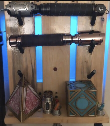
Yes it can be done. It’s how I setup a couple of the backlit and accent lit saber stands and accent lit smuggler’s coaxium cases with the chargers included. I just built them out with a diode and a switch on the parallel wired lighting side so only the connector gets the charger power and only when the board is off. You can just barely see the charger output wire as well as the wiring into and out of the blade plug.

2 Likes

Thanks guys. This is all great news. It means I can build the charge facility into all my hilts as standard so people have the option to use it if they want without it affecting any other functionality. :+1: :slight_smile:

The only tiny caveat I can see is that I often use data 1 for accent arrays to save adding another resistor on the array data line, then use data 2 or 3 for the main blade as the Shtok blade connectors have a resistor built into them as standard. But that’s a tiny consideration.

Thanks again guys. I appreciate all the info as always. :slight_smile: :+1:

One more question:

What kind of tolerance does the Proffie allow for in terms of blade ID resistor values?

For example, I just ran scanid with two different normal blades - one returned a value of 69 and the other 54.

Presumably if I use a 20,000 ohm resistor when I make my charging blade plug, scanid will return a figure close to that value, which is miles away from the blades.

But does the fact that both blades are sightly different from each other mean that one will work and one won’t be recognised? Or does the Proffie simply assign the settings based on which value the inserted blade is closest to, but it doesn’t actually have to hit the exact value?

I hope I’m making sense. :neutral_face:

To add further potential for thought food: if you replaced the 3 pole Neopixel connector with a 4 pole “ShtokCustomWorx Battery and Speaker PCB Connector”, you could also potentially upload new code/configurations to the Proffie board through the blade connector.

1 Like

ProffieOS has defines which specifies which code to use for blade ID. Because the Proffieboard CPU can’t do pullup at the same time as analogRead, the default is a sort of capacitance measure which outputs a voltage for a little bit, then quickly changes to analogread to see what value it gets. This method generally gets different values for different resistors, but they are not usually aligned with the actual resistor values, and the precision is unknown.

Now if you add a pullup resistor to data1, you can tell ProffieOS to just use analogRead() for blade ID. Then the values should come out close to the resistor values, and with a little calibration, they should come out within maybe a percent or two of the real value I think.

Unless you have a lot of blades, I would probably stick with the E6 series of resistor values:
6.8k 10k 15k 22k 33k 47k 68k 100k. These are all ~40% apart, which should make it very easy for proffieOS to tell them apart. Also, they are standard resistor values, so they are easy to find and come in every resistor kit you can buy pretty much. (If you do have a lot of blades, use the E12 series instead.)

After computing the blade ID, proffieOS picks whatever entry in the blades[] array is closest to the ID, so the value doesn’t have to be exact at all. If you only have one entry, then obviously that one is the closest… :slight_smile:

2 Likes

Legend as always Prof! Thank you so much for this - that clarifies everything.
My blade plug charger parts are 3D printing as we speak. Can’t wait to get it all working. :slight_smile:
Thanks again.
:slight_smile:

1 Like

OK I’m slightly puzzled: I’ve built my charging blade plug with a 10k/ohm resistor between data and neg. I checked the resistor with a meter before I wired it and all good.

I’ve now fitted the plug in a hilt and run scanID, and it returns a value of just 36. It makes no difference if I have the Proffie powered by the hilt battery or just the USB, the ID value is the same.

This seems at odds with the manual which says that I must run scanid with the Proffie powered by a battery, and further suggests I should expect a figure in the thousands with the highly resistored charge plug. For comparison, a normal 126 pixel blade returned a figure of 69.

Is there anything I’m doing wrong, or is that 36 the correct number to add to the config?

Sounds like you’re doing everything right. The only weird part is that you’re getting the same number with and without the battery.

Do you have something like this in your config?

#define ENABLE_POWER_FOR_ID PowerPINS<bladePowerPin2,bladePowerPin3>

Assuming your blade is connected to LED2 & LED3 of course.

Yes I have that define line, and the hilt is a very simple single blade job that is indeed wired to pads 2 and 3. I also have the Shared Power Pins define line, as the manual suggested it might be needed, although with only one blade I can’t imagine it would be but I thought it wouldn’t hurt to add it just in case. Blade connector on the hilt is a Shtok Eco which is set by default to run in parallel with the blade. I haven’t made any changes to the hilt wiring - it’s just the charging blade plug that has the resistor mod between data and blade neg.

Well, as long as the values are relatively stable, you’re fine, and you can use them. If the values were unstable, or too close to each other, then you would need to use a pullup resistor and some config changes to get better values.

The values do seem stable, but they’re also very close to each other. I tried two separate blades, one slightly longer than the other, and they gave values of 69 and 54 respectively. If the charger plug is 36 it seems awfully close. But I’ll give it a go.

Forgive my ignorance, but what is a pullup resistor and where would it go if I needed one?

The pullup resistor would go between Data1 and 3.3v.
It should be somewhere in the 10k to 50k range.
Then you would add this to your config file:

 #define BLADE_ID_CLASS ExternalPullupBladeID<bladeIdentifyPin, 22000>

(Replace the 22000 with the resistance of your pullup resistor.)

WIth these steps, the blade ID should come out close to the actual resistor in your blade.

Hold on - I think I know what I’ve done wrong - missing link in the blade pcb. Hold on while I grab my soldering iron…

Ah no, it wasn’t that. The plug was correct - 10 k/ohms when measured between data ring and neg ring.

Not sure if it’s relevant, but the manual seems to suggest I should get something like this in Serial Monitor when I run scanid:

Power for ID enabled.
Turning on FETs
ID: 448 volts 1.44 resistance= 23666.67

But instead what I get is this:

20:19:21.006 → ID: 36.00
20:19:21.006 → blade= 0
20:19:21.006 → WS2811 Blade with 132 leds.
20:19:21.006 → Failed to open: presets.ini
20:19:21.006 → Failed to open: presets.tmp
20:19:21.040 → Style RAM = 504

Relevant?

The extra information is from debug printouts that I removed a long time ago.

Ah OK, thanks Prof. So the response I’m getting serial monitor is correct and that 36.00 is the right number to read then. :+1:

OK, so I’ve done now some actual testing and it works, even with the similar values. :smiley: I’ve made a custom charging font folder which has a “Charging Diatium Power Cell” announcement as its boot wav so you can tell straight away that it’s gone to the right thing. :+1: :slight_smile:

But as you’d expect, I still have a couple of questions (LOL! Sorry - too curious for my own good once I get going! :smile: ):

  1. So it’s the boot process that actually detects which blade is fitted. If you fit one blade, boot the saber, remove that blade then fit the charging blade, it won’t recognise the charging blade until you power down and reboot. That seems to be what mine is doing. I’m guessing there isn’t a way to have it so you can hot swap blades without needing to reboot?

  2. in order for the charge facility to work the blade has to be on. However this means the LEDs on the Shtok blade connector have to stay lit while charging. I’m guessing with only a handful of LEDs in those connectors, heat buildup won’t be an issue, but it occurs to me that if I were to set the charging blade LED count to zero, but still tell the config to have the blade lit, this would power up the fets for charging to work, but no Shtok LEDs would actually light. Or have I got that wrong?

The only other thing to add is once again my sincere thanks for all your help Prof. It’s almost becoming a cliché to say it, but your efforts are very much appreciated. :slight_smile:

1 Like