The thread on Wireless Charging, led to the thread on Blade Plug Charging, which resulted in an excellent proof of concept by Sabersense. Now that blade plug charging is a viable option the concept of a saber you never have to open is becoming more and more apealing.
A USB connection has 4 wires (Positive, Negative, Data + and Data -).
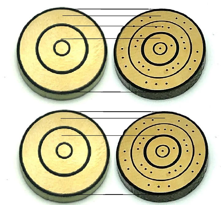
The “ShtokCustomWorx Battery and Speaker PCB Connector Set” has 4 poles (Positive with 5 pins, Negative with 5 pins, Speaker+ with one pin and Speaker- with one pin) and is the same diameter as a blade connection PCB.
A blade connection PCB uses 3 poles (Positive, Negative and Data).
You could pretty easily use the Battery/Speaker PCB as a blade connector (change the standard 3pole blade connector for the 4 pole blade connecter at hilt and blade), but in order to use it to upload programming you would need to double up wires on one of the speaker poles. My question what would happen if you connected the data wire for the blade to the same pad as the wire for the USB data (Assuming you were never trying to activate the blade and upload programming at the same time)? Would this be doable or would it fry something?
I would imagine that you could also have a blade detect setting that would just turn off the option for a blade?
It may be possible to make it work, but I’m not sure it would be a good idea.
For one thing, it wouldn’t work with any of the thousands of existing blades.
The 3-ring connector is now a standard which lots of sellers use, and changing it is unlikely to get a lot of traction.
Second, it means that you can’t see what you’re doing when you’re using WebUSB to make changes. Maybe a minor problem, but still a problem.
Might be easier to just make a pogo pin PCB which also has an USB-C connector in it. I think there might be enough space…
Do we know what the current rating is for each pole in 3pole and 4pole connectors? I’d want to figure that out before changing, as more poles might mean less current capacity per pole, depending on number of pogos and vías, etc. disclaimer: I’m not an ee, so I don’t know what I’m talking about as a general rule.
“Well, I dont use WebUSB much” I said to myself and then spent an hour using it to fine tune my saber presets last night…So, I guess we will see how much of a pain it is to not have a visible blade while connected to the saber.
I was mostly concerned with any possible damage that may happen to the ProffieBoard. Since your first concern wasnt “You’ll burn out your board for sure” Im guessing that is a minimal concern.
I make my own blades, so the industry standard is less of a concern, but definately a concern for most and me if I ever want to try out somone elses blade.
Making a custom PCB for the hilt side that works with the standard 3 pole blade PCB may be something worth pursing. Im looking into that as well.
Per Saber Armory “These connectors support 15A continous and 20A burst.”
They also have 5pins on positive and negative rather than 5 on negative and 4 on positive like the standard blade connector, so power shouldnt be the problem.
Per the entry on SaberBay the NPXL V3 Longpin Connector is “Rated up to 18 Amperes max (up to 15 Amperes recommended) without current losses”, so 15amp continous and 18amp burst. Which is honestly a little odd because elsewhere I have seen the Pogo pins rated at 2amps and 3A burst per pin, which is 10 and 15, so ¯_(ツ)_/¯
Guess it would make sense that the 4 pole PCB can handle a little more power since there is an extra pogo.
Some one-inch blade-side pcb holders have a recess for a mag-connect ring, which is a magnet that helps hold the blade in place. I don’t think it ever really took off as a feature, but it shows that there is room for a thin extra outer ring. This means that if you are going down the road of making new custom neopixel pcbs, you could make them to be fully compatible with normal three-ring blades by adding the extra data ring to the outside. The new pcb holder would need to be deeper to allow for internal wire in the blade plug adapter to the outer ring, but that’s easy to do.
The downside of course is that this depends on having custom pcbs made. I’ve no idea how expensive that is or how many need to be made to make it viable, but it’s worth thinking about as a fourth ring opens up various other possibilities.
That is a good point. If (when) it gets to making a custom PCB, it wont be limited to 17.5mm diameter. My saber is made a little weird in that it is almost a thin neck. The neck is JUST big enough for a standard 17.5mm blade connector and thats it. So, I have a knee-jerk reaction to anything over that since it will mean an internal adapter.
The ideal solution would be to have a 5 pole hiltside PCB that will also works with a 3-pole Saberside PCB. Since a 7/8" blade gives us a little over 22mm to work with, it should be relatively™ easy to make a custom PCB that adds 2 poles onto a 17.5mm hiltside connector. Honestly, that will probably be the end goal. Once there is a working prototype we will essentially have an all-in-one solution for charging, updating, having a blade to see for WebUSB and still keep compatibility to all the pre-made blades on the market…so thats pretty cool.
I just ordered a couple of the battery/speaker PCBs and will hopefully be able to start experimenting with those soon and verify that updating over Pogo connections will work (dont know why it wouldn’t).
Im also curious what will happen if I send programming data to the blade data pin or blade data to the USB? Basically if there is no harm (wouldn’t cause damage to the electronics) in sending data meant for the blade to the USB data or sending data for the USB to the blade, then the all-in-one solution would be achievable with the currently available 4-pole PCB, you would just have to change your blade to 4-pole as well to avoid shorts.
If you know this will cause damage (or wont), please say something.
And in case you are curious, this is how the 3 and 4 pole PCBs line up.
The blade pin has a 470ohm resistor on it, which should protect it from such damage.
The USB pins only have 22ohm resistors on them, which helps, but is not enough to protect them from shorts completely I think.
Another thing that occurs if designing a new pcb is having a male locating lug on the outer ring blade-side pcb with a corresponding female socket on the hilt-side pcb. Since the outer ring will only ever be used for blade plug adapter functions (programming etc.) such a socket in the hilt side wouldn’t affect normal blade connectivity. But the fact that it locates the blade in a given orientation means you could divide the outer ring into several segments, meaning you could have USB data + and - without interfering with the main blade data pin. You could also do stuff like running the battery through the pcb then back to the board on one of the segments, so that the board is only powered when a blade or blade plug is fitted as it would short the two segments together, thus doing away with the need for a kill switch. This really would start to free up design possibilities for amazing looking chassis.
a neat thing that could be done, which I thought of a few years ago for a slightly different application, is that you could have the outer ring segmented and then figure out which pins are connected to which pads after connecting. Simply send a query over each pin and see what you get back. There is a potential problem of a pin landing smack dab in between two pads, but if the pitch of the pins is different from the pitch of the pads, say 15 pins and 16 pads, then I think you’d only end up with a couple pins contacting more than one pad. And if we have an excess of pads, it’s ok if two share a pin. So if I need 5 total connections, and I have 15 pins and 16 pads, I bet I’d be able to find at least 5 signal paths. That would of course require more gpio than strictly necessary, and thus would be wasteful, but it might work when we don’t know the orientation of the blade. A better solution would be to add some kind of keying to keep the pads and pins aligned with each other. That could be done by giving the pads a concave surface, so that the round tip of the pins wants to settle into it, or by other means like the rod that shtok uses on his … was it 12 poles?.. his really connecty connector. You get my point.
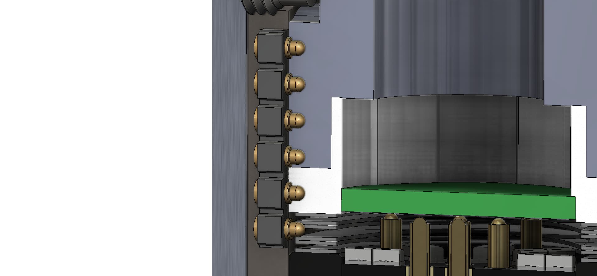
ok, so you’ll have to use your imagination a bit with this one, but see the below image. It shows that there is in fact SOME room for a pogo pin of this type in MHSv1 saber bodies. Ignore that there are lots of them and suppose that you had just two or three pins.
EDIT: Another way to do it might be to put the contacts in the hilt, in the form of stacked rings, separated by insulators, and wire directly to those. then put the pins on the plug, since we have lots of room in that, and control over placement of the pins.
Keep in mind that all sabers have an easily usable blade orientation index in the form of the set screw that tightens onto the blade. Just screw it in a bit, have a channel in the plug and Bob’s your uncle.
As far as not having to put a power disconnect in, maybe look at a magnetic disconnect. Ie, use a magnet placed on the outside of the hilt that reacts to another magnet that disconnects the power to the battery. Essentially a relay.
Unless someone knows of a way to protect against that, the next step will be to start looking at a custom PCB. On the plus side it should be easy enough to add a 2-4pin ring around the standard 17.5mm blade contact and keep it under 22mm.
If you are willing to make a new PCB, then there’s an easier way of doing it: just add some hard pins to the data plug, and standardize on some hole in the hilt’s PCB that take that pins under the PCB plane. That change would be backward compatible to all blades, and the data plug would simply make no contact with old style PCB’s if the fixed pins are long enough.