Based on the discussions by @Sabersense and @profezzorn on this thread I decided to make a first version of the charging bladeplug. Apparently TCSS went with doing it in stand way. But my design requires just 1 3D printed piece, and the rest can be made with common blade parts.
Caveats
Let’s start with some basics:
- This only works with Plecter Labs/TCSS/ShtockCustomWorx-style NeoPixel connectors.
- The hilt has to have Battery + wired directly to the NPXL connector and the negative has to only have FETs between them. As such, we have validated this with Proffieboards but I don’t know about the other soundboards.
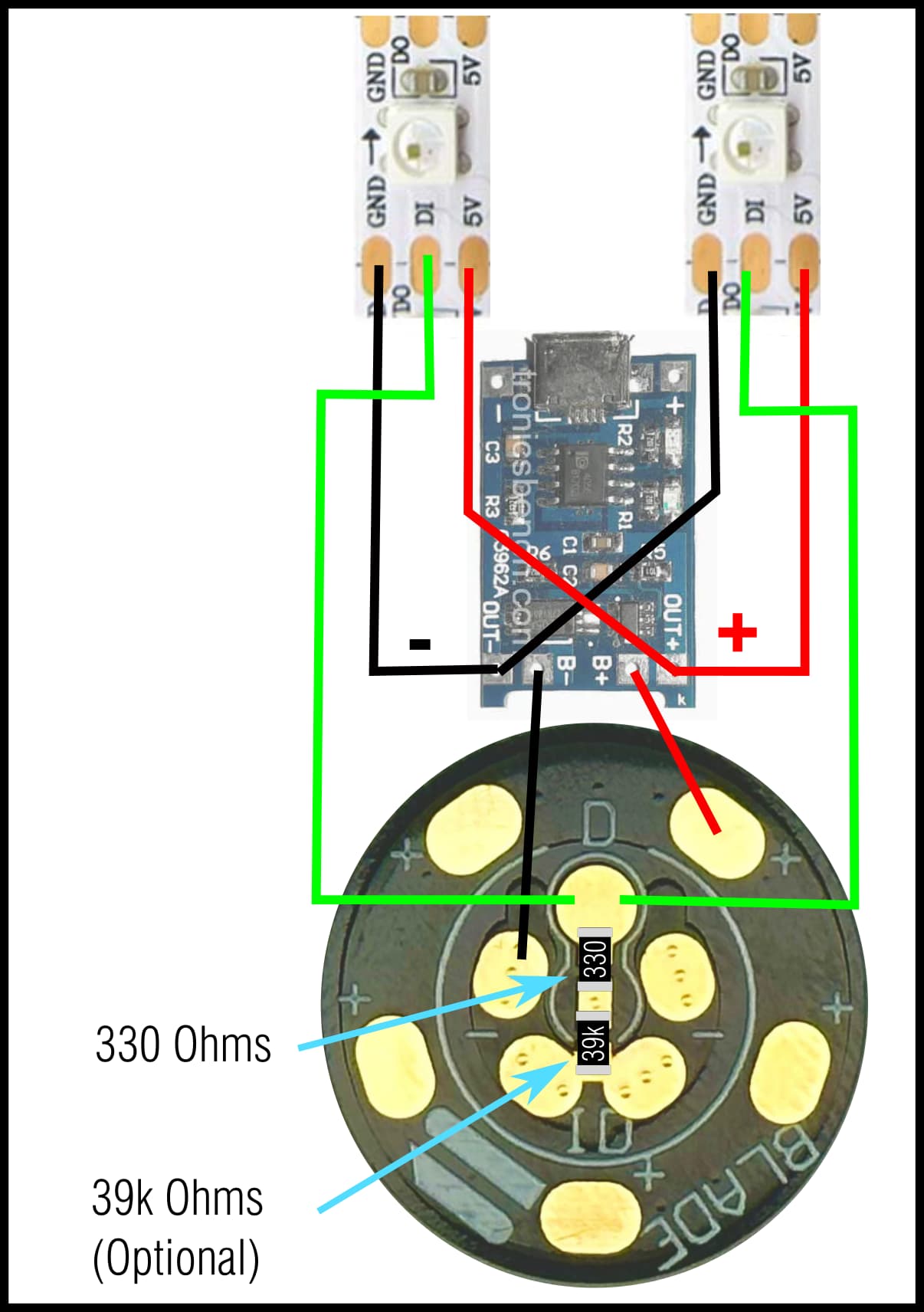
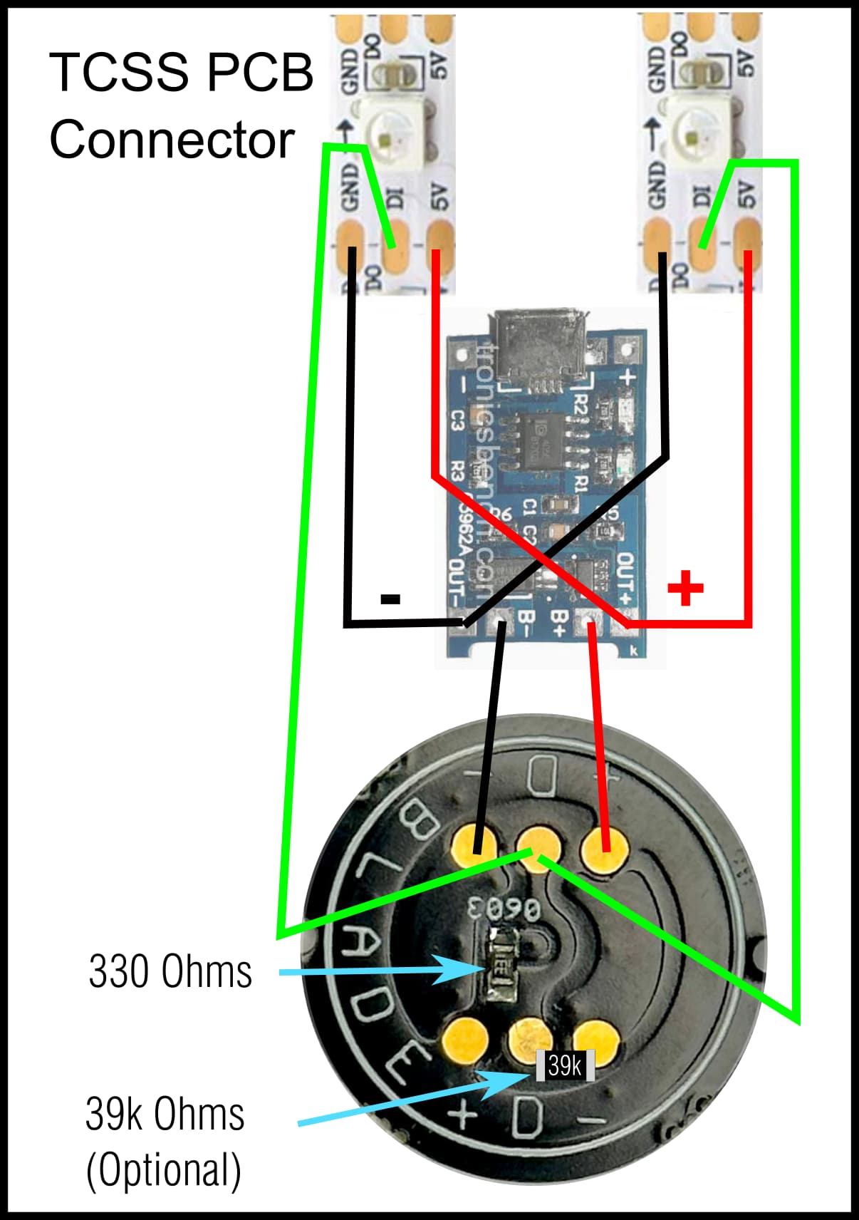
- In this implementation I used a particular but pretty popular TP4056 USB-C module for practicality reasons. You could use anything that charges a Lithium-Ion battery. But I can’t stress the need for protection circuits in general.
- Most lithium ion charging modules depend on current to know when the battery has top off. Thus, it is important to minimize consumption while charging. Since you need the Proffie to stay on, you want to have it detect the blade (I used a 39k resistor) and make a minimal preset with no sound that turn’s off every other blade and element. In my implementation, I chose a module that has OUT lines to feed the neopixel leds off the charger.
- I’ve tested one charger with one Proffie installed saber with a completely depleted battery, where the board wouldn’t even start up, and the charger worked. I can’t assure that it will work with every board, and may be a different manufacturer of the charging board might not work with a turned off soundboard. But the only test I did, worked.
Now, to the particulars of my implementation.
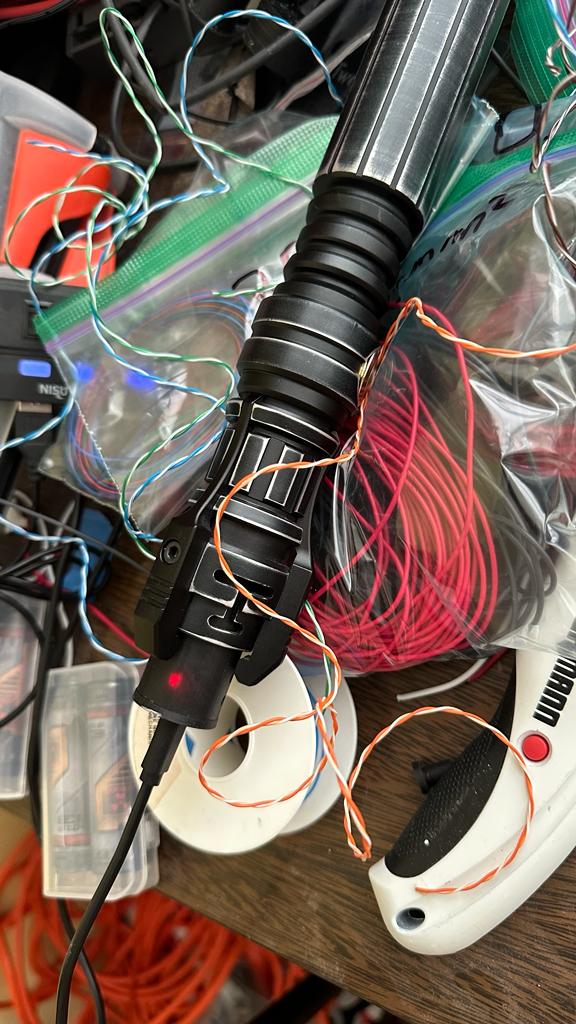
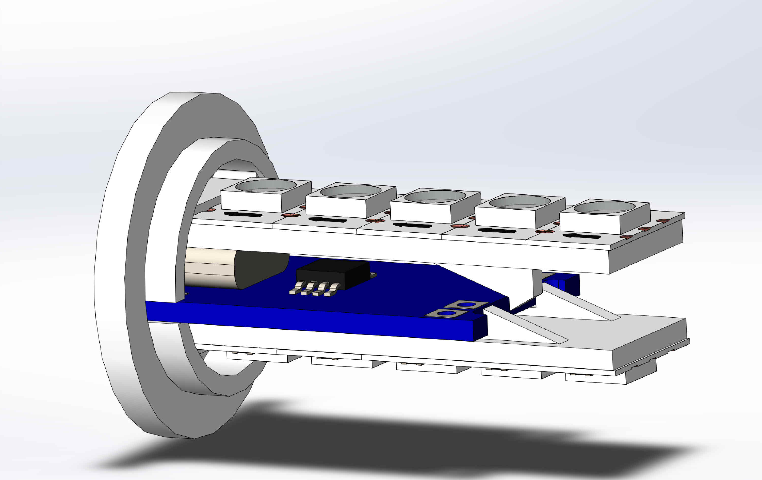
Blade Charger V1.0
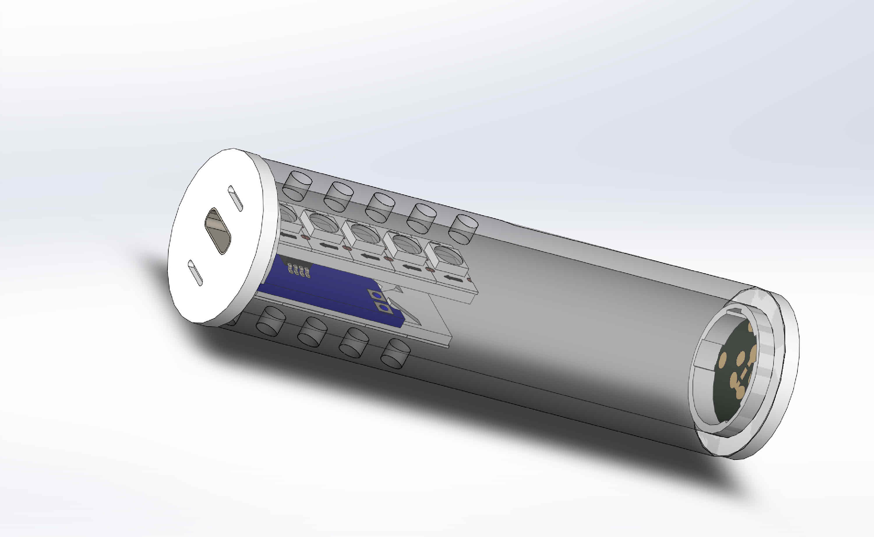
I’ve designed it so you can use any piece of blade tube and connector adapter. But, I made my own tube so I could undersized it so it will be a loose fit on every hilt. Some are ridiculously undersized and require a lot of sanding for blades to fit. And since I wanted this to be as universal as possible, I just printed my own. Since I’m assuming that you will print with opaque stock, I added windows for the LEDS.
I’ve chosen to just have a 5 strip of 5050 WS2812B 144 px/m, which is what I use to make my blades, but 3535 should work just as well as long as you use 144px/m strip. I decided on 5 elements because I like to cut my blades to 124px and I can do two chargers with what’s left.
Since you have to minimize power consumption while charging, I’ve added a 39k Ohm resistor between Data and Negative, so I can use Blade ID to turn off every blade but the main blade. Note that when I install my Proffies I always add a 22k resistor between Data1 and 3.3v so I can use the “true” resistor values for Blade ID. If you don’t, you will first need to measure the resistor value from your Proffie and input that value into your preset. If you don’t want to set up blade ID, I recommend that you set a charging preset and just plug it in that mode. You will probably not even need the LEDS in that case, and if you used a blade tube, the charging module’s lights for charging and done will be seen through.
I’m adding 1" thin, 1" thick and 7/8" thin versions of my charger. I also have made TCSS and ShtokCustomWorx PCB adapters. You should use normal blade PCB and not the ones with LEDs so you don’t add consumtion to the charging line. In the modules I use it needs less than 1/C (100mA for the stock implementation) of current to stop the topping off process. Each NPX might draw up to 60mA, so no pixel should be on the line.
You could just use a scrap of blade tube, the corresponding PCB adaptor and a PCB and just print my top and you would have everything.
For wiring you will need to be able to carry a bit more than 1 Amp, anything 29 gauge and above should do it. I usually use a little scrap of Category 5a or 6 UTP cable, and use those pairs. They are gauge 28 and have really thin pvc, so they are amazingly practical for saber intalls. Please remember that you can’t use them for anything power hungry (i.e. anything that feed a Cree, TriCree, NeoPixel nor Soundboard).
Parts List
1 x AC to USB-C power charger with cable. You should have many of these laying around your house for your phones, tablets, etc.
1 x USB-C TP4056 module with both BAT and OUT pads. (mine is HW-373 V1.1, others are marked 03962A, just buy one like in the pictures). Reference size is 28mm x 17.35mm board (the USB-C connector adds 1mm).
1 x Neopixel blade-side PCB connector WITHOUT LEDS but with the 303 Ohm resistor.
1 x Blade PCB adapter.
1 x An 85mm (3in plus 3/16") long piece of blade tube (optional).
1 x An 39k resistor 0603 SMD or really small carbon one (optional)
2 x Five pixel WS2812B strip (either 5050 or 3535) 144 px/m.
1 x 3D printed charger top.
28 gauge or thicker wire.
Steps:
-
Print whatever pieces you will need.
-
Cut and sand tube to size (85mm), or just use the printed tube. When you cut the WS2812B try to cut so the first element, has some extra connector from the previous one. It won’t be needing it and it will help you to solder later on.
-
Add the PCB blade connector resistors. Inline in Data use a 330 Ohm. Between Data and Negative use a 39k. Also pre-tin the PCB pads that you will use.
-
Solder first all the wires to the TP 4056. Then pre-tin the two WS2812B strips and the PCB side connector.
Use 10cm to 12cm for the wires that go from BAT to the PCB connector.
3 to 4 cm for the ones that go from OUT to the WS2812B PWR and GND.
And cut 10cm for the ones that go from the WS2812B Data to the PCB.
It is easier to twist together the tip of the two wires that go to each OUT pad first and then solder them together at the pad in one go.
For the Data solder one wire to each Data line and then join together both tips that will go to the PCB connector. -
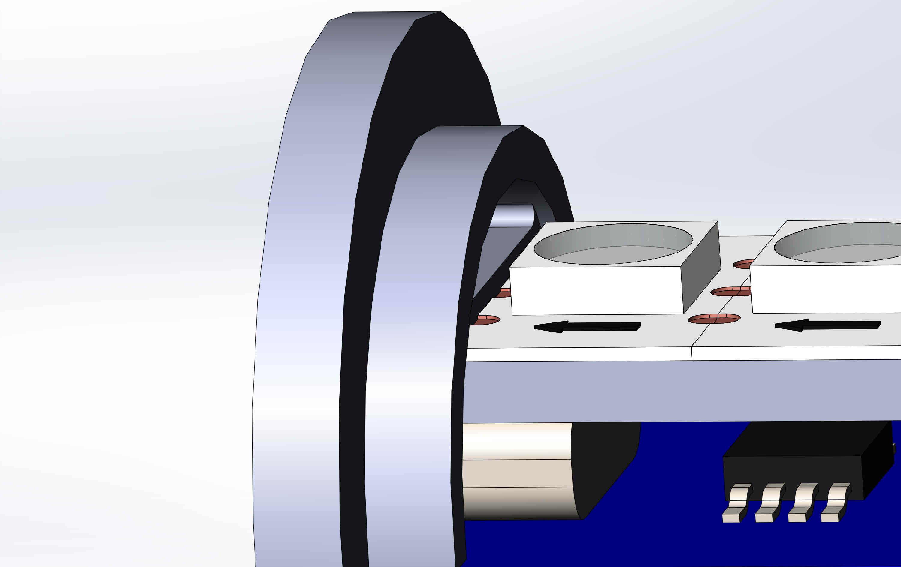
Insert the TP 4056 module into the head (is easier if it enters sideways).
-
Remove the protective strip from both WS2812B strips and glue them on each side of the top piece as shown in the picture. REMEMBER TO POINT THE ARROW TOWARDS THE USB-C Conector SIDE!! Please note that I’ve added a stop so you can align them perfectly to the tube’s windows.
g) -
Solder power and data to both pixel strips and introduce into the tube.
-
Pass the wires down the tube and through the PCB adaptor. Then solder power and data to the PCB connector. Without adding glue, press your PCB into the adaptor, put the adaptor into the tube.
-
As discussed before, if you want to depend on Blade ID to recognize the charging plug, you have to configure your hilt. For Proffieboard, you should add the following line to your blades[] definition:
BladeConfig blades[] = {
(...)
    //Charging Blade
    { 39000, //Or whatever resistor you put between Data and NPXL negative
        WS281XBladePtr<5, bladePin, Color8::GRB, PowerPINS<bladePowerPin2, bladePowerPin3> >(), // Charging Blade with 5 Neopixels
        //Plus whatever other blades you have defined, like any illuminated PCB or crystal chamber.
        CONFIGARRAY(presetchargeblade)
    }
 };
Remember to add your other blades, like illuminated PCB or crystal chamber to that definition.
Please note that I’ve added a new preset setting presetchargeblade.
Now to add the new preset. I made a font directory called PwrCell and just added font01.wav and boot01.wav. No other sound means no extra power wasting. Then edit your presets section with a the new preset.
//----------------------------------------------------------------------------------------------
// For the Charging BladePlug
//----------------------------------------------------------------------------------------------
Preset presetchargeblade[] = {
	{ "PwrCell", "tracks/mars.wav",
		&style_charging,
		//Also black out any extra blades with StyleNormalPtr<BLACK, BLACK, 300, 800>(),
		"Blade Chrg\nLevel"}
};
I did it this way because I have Blade Detect wired in my hilt. If you have a killswitch or an on/off switch, you will need to turn off the hilt, introduce the plug, and then turn it on again for charging. And after charging, you will have to turn it off, swap to your favorite blade, and turn it on again.
Now, recompile, upload, and star up your hilt.
10) First plug the AC to USB-C on the wall, then on the charging bladeplug. Then introduce into the blade port, press firmly. You should see the first lights. If so, just screw the hex nut to keep the bladeplug in place and let it charge your blade.
11) If everything is working properly, just add some glut to the top and PCB adaptors and close it definitely.