Hi All
sorry for pestering on this again but i’m still struggling to picture how this all works(i struggle to absorb words but diagrams and actually doing always helps me), i might have to much info about it in my brain now also so hoping i can get it sorted ![]()
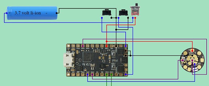
this is currently how i am wired up(V3 board) except i think my neopixel connector is v2 style as only using data2 and both resistors are still there for parallel leds, data2 is wierd to data1 on the proffie though
now this is where i get confused and info overload for me, i was wanting to implement the blade charger with blade id enabled and this is where my brain goes to mush
“so I can use Blade ID to turn off every blade but the main blade. Note that when I install my Proffies I always add a 22k resistor between Data1 and 3.3v so I can use the “true” resistor values for Blade ID”
a reply from the man himself profezzorn
“Yes. It also requires a small configuration change to use the right blade ID class:”
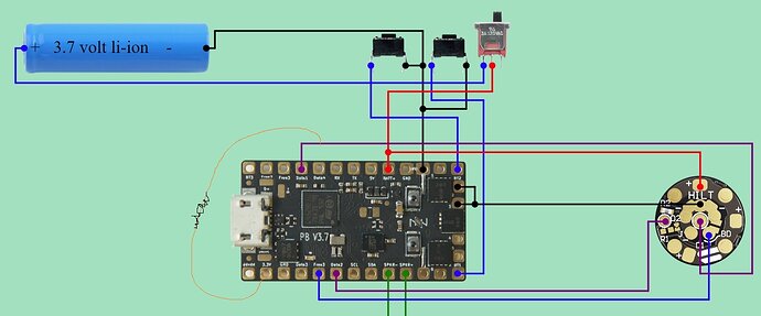
so this is how i think it’s done excuse my jedi level paint skills lol
it feels wrong to me to just wire something to +voltage but have the bits needed to do so, but i then came across this for V3 listings to purchase a board
- Two CPU pins are already tied together for Data1, making blade ID work without additional components
is nothing else needed now for v3’s or do i still need the wire from 3.3v to data1?
thanks for looking and sorry if this post is hard to read

