Dumb question, but how do you manage to remove and replace tiny components right next to other tiny components (like the row of 3 diodes in your D61 swap example) without totally scattering the other components?
3 Likes
Interesting method. I’ve always figured that if you have a good hot-air station, you could set the air flow really really low, and then the components wouldn’t blow away.
Most hot-air stations seem to focus on really HIGH air flow though. Not sure why.
I have no idea what sort of CFM the lowest setting mine does, but it’s pretty good IMO.
I have not blown other components off without the tape, I just like to reduce the chance of also melting their solder and/or bumping them off their pads as I work in a tight space.
I dont understand it either. 35% airflow on mine (what it comes set at out of the box) will blow any non-fastened components away and splatter solder paste everywhere.
What temp do you usually use? Im afraid of going too hot and damaging other things but when i have my airflow set all the way down it takes a painful amount of time to melt.
I have mine set to 350 and just start hitting it as soon as I turn it on. After 30 seconds or so I start grabbing it with tweezers and applying gentle lifting pressure and that usually comes off about a minute I guess?
It’s kind of like how I cook. I don’t believe in preheating an oven. I just throw the chicken fingers in as soon as I turn it on set it to 450 and it’s ready in 15 minutes.
2 Likes
“Cooking” “chicken fingers”… haha.
Honestly, though, I think this is my favourite thread on the forum.
2 Likes
4.0 volts on main pos and neg pads on proffieboard when hooked up to battery.
3.3 volts on 3.3 volt pad.
Port not recognized in arduino. But I can force upload by putting it into bootloader, but then if I power the saber off, I have to force upload via boot/reset bootloader again to get the board to come back to life?
Once you kill power, you have to put it into bootloader, force upload again, then its all good again until you remove battery power…
This one is in an installed saber. Any guesses?
It doesn’t boot normally when connecting USB power?
Typically, if D61 diode is bad, you can not boot from battery power alone. USB power allows boot, then while saber is running, you can disconnect USB and it continues to run on Battery fine until kill power.
Sounds like you’re saying it’s completely unresponsive until you force bootloader mode and upload again.
precisely, havent heard you with one symptoms like this.
If you plug it in to USB, then press reset, does it work?
No, you have to put it into bootloader and force upload for it to function normally again. Everything is fine, until you kill power. Then it won’t re-boot.
Weird.
If you put it in bootloader mode and then press reset (no programming), then does it work?
Fredrik,
I had a Red Bear Nano 2 on it, and had positive wired to SD power like in the diagram on the proffieboard page, that was causing it. I switched positive to 3.3 volts, and issue went away, and blue tooth is working. Sorry to hijack Brian’s thread. All fixed.
1 Like
Good news, good find. Thanks!
That’s still strange, but definitely good to know.
Okay, back at it and this time a 1.5 board.
However, I’m getting stopped right out of the gate with multimeter beeping continuity when connecting USB. It’s fine just sitting on the test bed. This is a first for me.
As per the test script instructions, I’m stopping here before applying battery power, but not sure if I can even do anything about it.
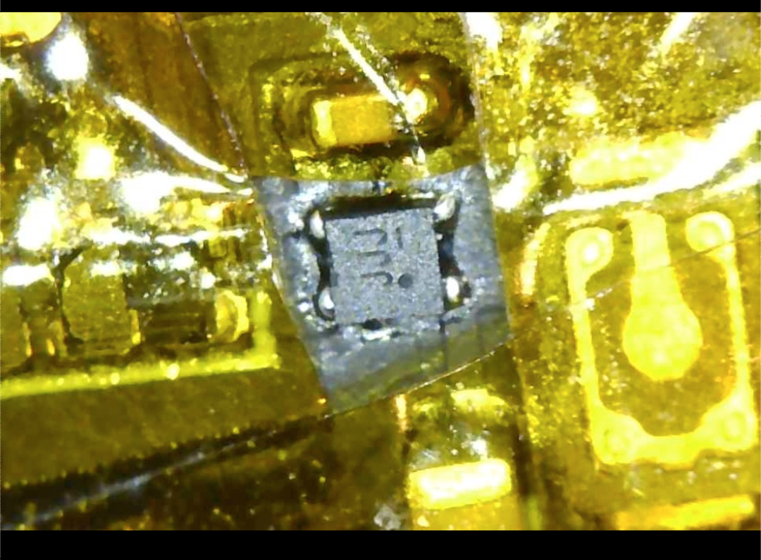
I checked the D series diodes, and while I’m not sure why I’m seeing the numbers I’m seeing, all three of them are the same, as well as on another working 1.5 board.
Diode test mode, 1.7V red to anode, .18V with a beep when reversed.
I’m assuming it’s something internal in the CPU, at which point I could attempt swapping that… Or just apply battery power and watch a firework show possibly.
@profezzorn, thoughts?
So you’re measuring a low resistance between + and - on the USB?
What about BATT+ → BATT-? is that also low?
If I remember correctly, there are only two components that are hooked up to both VUSB and GND: The CPU and U40. You could try removing U40 first to see if that helps. It’s far easier to replace, and the board can generally work without it.
It’s probably the CPU though.
No. nothing like that measured. Just the D61 D62 D63 schottky diodes.
The continuity beeping is from having the meter set up as an alarm, connected to Pos and Neg on the test rig board.
Also, while it was briefly connected to Serial Monitor, I got “Short on pin” for 17 and 24, and once a pin 0.
However, moving onto the next board(s) in line to test, I now have three 1.5’s all doing the same symptoms, but it seems like only when the 5v booster is active.
Maybe the script is weird for 1.5?
That would be weird since it was written for V4, and the same script (using V4 naming) is fine on V5 2.2 boards.
02:37:00.292 ->  Waiting for battery power
02:37:00.760 -> Short on pin 17 expected low with pulldown
02:37:01.261 -> Amplifier off.
02:37:01.298 -> Short on pin 0 expected low with pulldown
02:37:01.661 -> Short on pin 24 expected low with pulldown
02:37:02.323 -> Amplifier off.
02:37:03.056 -> Short on pin 0 expected low with pulldown
02:37:03.305 ->  Waiting for battery power
02:37:03.597 -> Amplifier off.
02:37:04.392 -> Short on pin 24 expected low with pulldown
02:37:04.749 -> Short on pin 17 expected low with pulldown
02:37:05.000 -> Battery voltage: 0.04
02:37:05.397 -> Amplifier off.
02:37:05.871 -> Short on pin 24 expected low with pulldown
02:37:06.237 -> Short on pin 24 expected low with pulldown