Ahhh, ok. I felt very inadequate there for a moment.
Ha
Who do you go through for rapid prototyping?
Ahhh, ok. I felt very inadequate there for a moment.
Ha
Who do you go through for rapid prototyping?
In this particular case, Khal (of The Saber Armory) made it.
Following this because as some here know I can find ways to bork and break stuff so when you need a heavy handed Jedi to play and beat up a trial piece let me know.
What is your estimate of when beta testing will be done and v3 in production? I’ve got a nov 2021 commission with star fall sabers and I’m wondering if it’ll be able to use the v3.
Beta testing hasn’t even started yet.
I’m still at the prototyping stage.
Things seem to be moving a bit slowly.
I wouldn’t wait.
I think you can replace those buttons with even smaller footprint (square) if need to save more space.
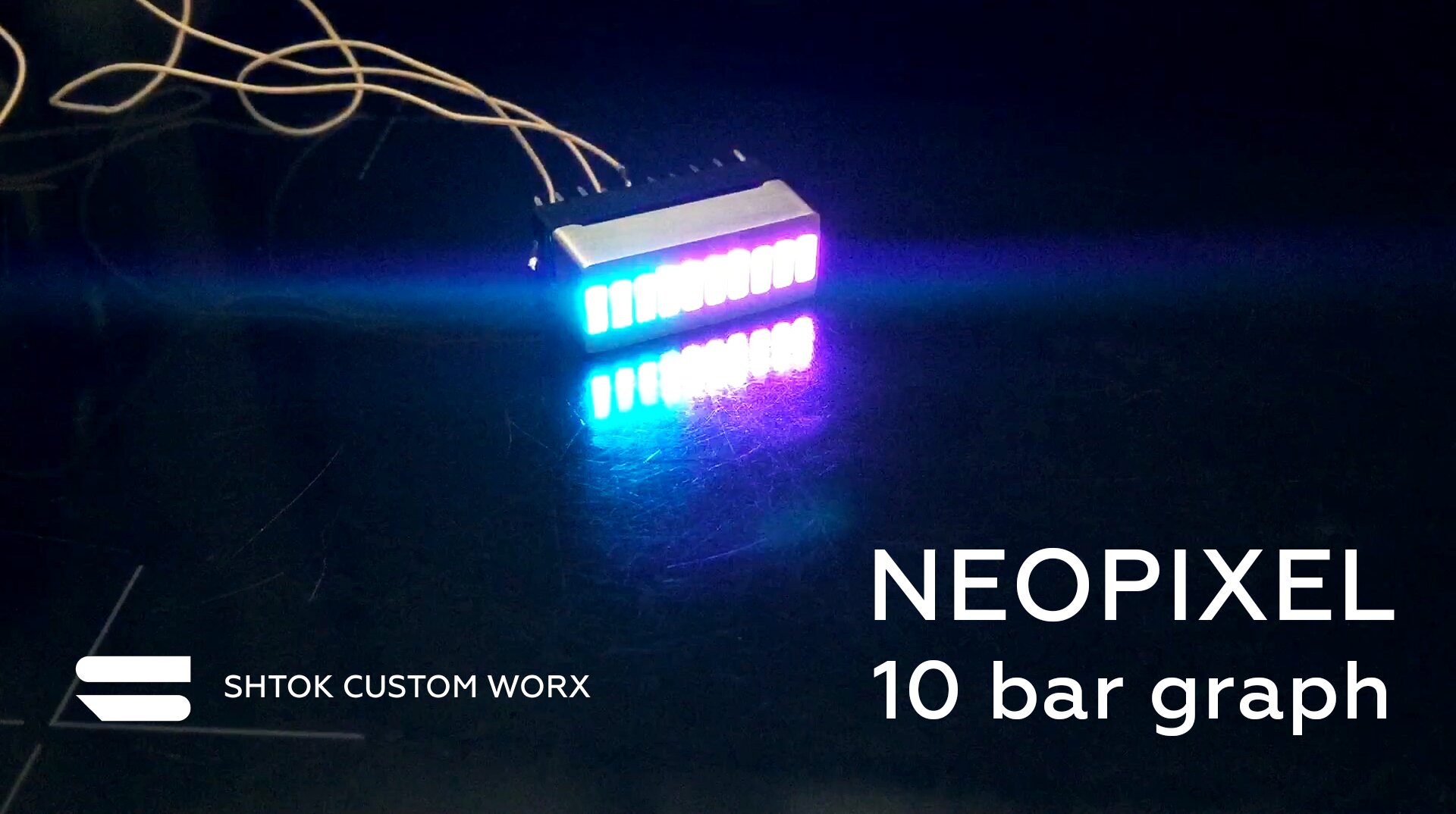
And it really would be awesome to have 10 PWM accent leds 18-20mA outputs for wiring a 10 bar graph displays (and independent control of each) like we can do with CFX. Even if those pads are tiny small, professional installers could still use them! 
And, although 2.54mm breadboard friendly pinout is cool, I think it’s better to have more pins for more functionality…
But why? 10 neopixels would be much easier to control, wire and use, and you would get RGB. You could even stick two or three 1.5mm neopixels next to each other under each “segment”…
I have a neopixel bar graph product in development for that, but using old school bar graphs is still cool 
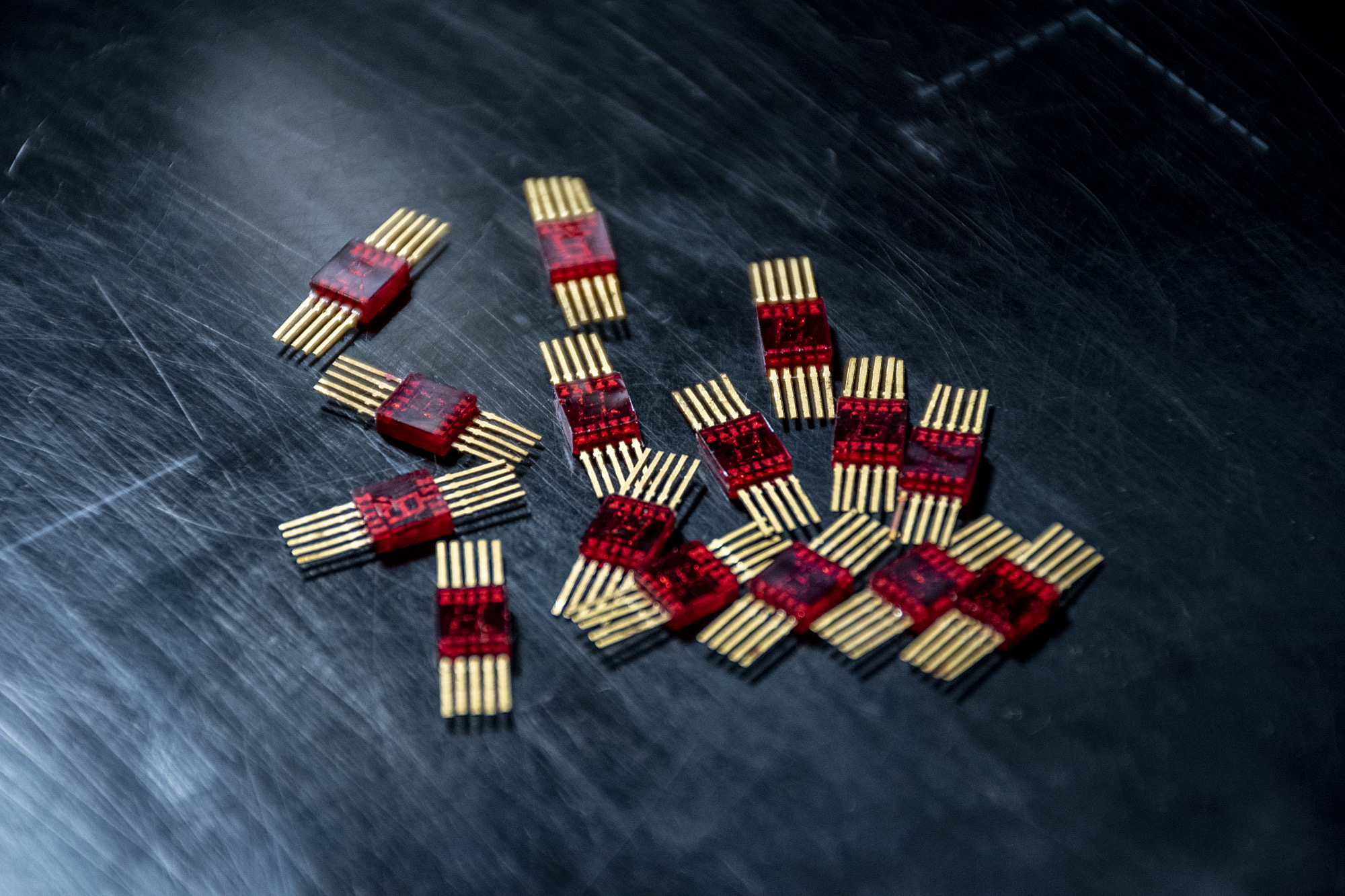
and it would help to control this kind of cool retro digits indicators:
I already got a bunch of those, they look awesome:
I think the right way to control things that needs that many pins is to to get some i2c, serial or spi control chips and then hook those up to the proffieboard. V3 will have a free SPI bus and multiple i2c buses available.
10 pins are enough though, they have 8 negatives and a common positive terminal, and when making an array of those, we connect all individual negatives together so still have 8 negatives and a number of individual positives.
Please take a look at this scheme, you may be interested.
Interesting stuff, but I think it’s in the wrong thread.
Please start a new thread for this.
Not ready for global discussion yet, this is just a rough draft. But it seems to contain some interesting solutions.
PCA9685 - I2C 16ch 25mA PWM led driver
Brian Conner sent me here from the Facebook group to make a suggestion. So, thanks for the invite. Also, thanks for all of the development you do behind the scenes, I personally appreciate it
One suggestion for a “feature” I believe would make the V3 just “that” much sweeter is if you broke out the “BTN” net onto a pad so we could literally wire in the “boot” button. Right now, on V2.2 we have the ability to wire an external reset button. But, I am thinking with the removable speaker setups available, putting “hidden” boot and reset buttons under the speaker so when combined with a short USB extension reflashing can be done WITHOUT having to remove a chassis.
99 times out of a hundred, you can flash the board without needing to access the boot button.
I always tell people that it’s ok to make it difficult to access the boot button, but it can’t be impossible. In principle I agree though. I might try to make a special pad for the boot button if there are more revisions to the V3 board. (Assuming I can find the space for it.). The pad will probably be internal on the board somewhere as most people won’t need it or use it.
Obviously, there is always the option to just remove the button and put wires there instead. Fiddly, but not overly hard.
Will (or could) the V3 have all component codes in the 3D view in KiCad? One thing that tripped me a few times was a few of them not being displayed in the 3D view (obviously you can view in the pcb view, but faster in 3D).
Edit: This is assuming I’m not just doing something stupid while viewing in 3D mode.