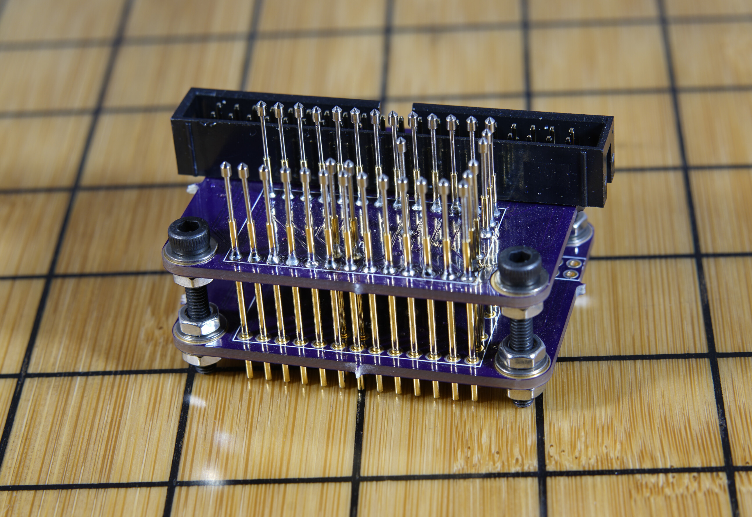
V3 pogo pin adapter. Hopefully final prototype:
3 Likes
Damn, that’s way cleaner than any test rig I’ve built…never seen pins like that before.
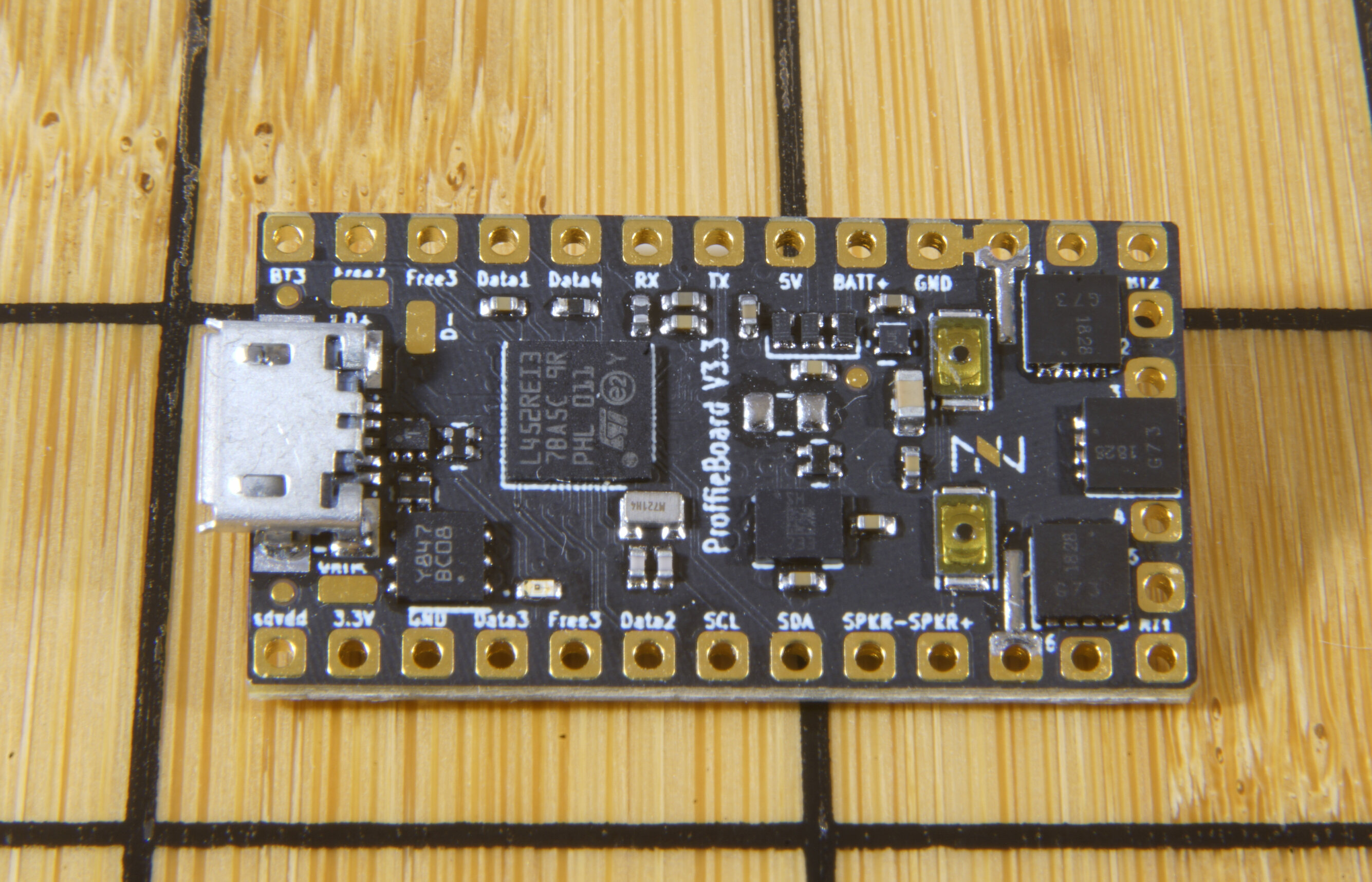
I’ve used the same pins for a while, here they are in 2017:
I’ve never found these pins on any normal place to buy electronics components, but I’ve seen them on ebay, aliexpress and amazon:
2 Likes
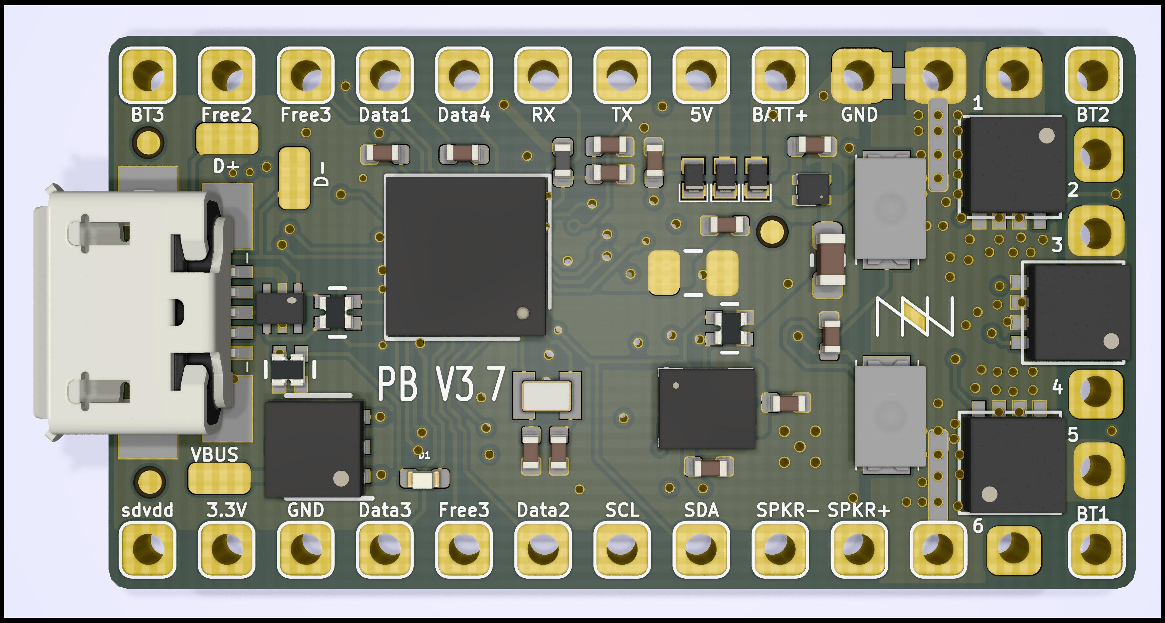
Because of having multiple people to work with, there has actually be a fair number of revisions to the board since the original rendering above. Most of the changes are minor and don’t actually affect the function of the board in any way, but I thought it might be nice to have an updated rendering:
Also, here is the bottom side:
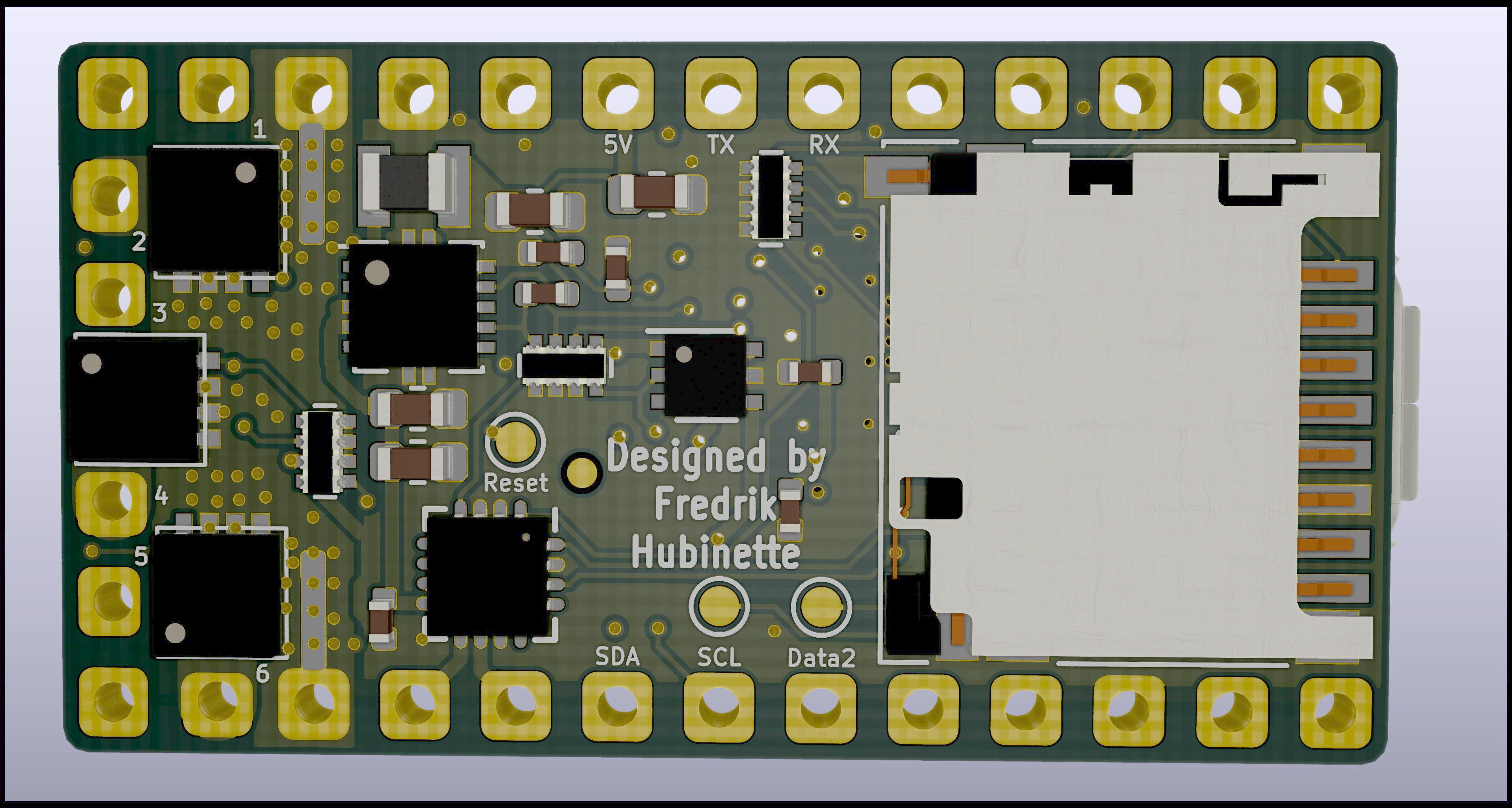
The bottom side looks quite similar to the V2.2 boards, but note the three new internal pads: reset, swdclk and swdio. Since these are mostly used for debugging and testing and very rarely in a real saber, I moved them to the middle of the board, which is how I made room for more useful pads.
You can see the matching pins on the pogo pin adapter above.
3 Likes
I notice buttons 1 and 2 are swapped around compared to the 2.2 board. Note to self to watch out for that little tripwire when installing.

Unless you are doing something weird, you can always work around that in the config file.
1 Like
Of course.
It was just an observation.
Can’t wait to find my way around it when it becomes available. It looks amazing. The lightsaber world is indebted to you as always Fredrik. 


Thanks Boss. I may have to throw together a test rig. Had to order new solder balls - my 5 year old poured mine out onto the carpet. No re-balling until they get here on the slow-boat.
Yeah, it’s been a morning…
Thanks for the updated render, too. Seeing the clock, dio, and and reset as pads and not through-hole is exciting…and is great to have more available “main” pads. How are free connected - via the CPU for data type mapping?
Free, Data, Buttons and serial pads really all just connect to the CPU.
The only difference is in capabilities and convention.
Any of those pads can be used for neopixel data, any of those pads can be used as a button.
However, only the button pads can work as touch buttons.
On the V3, the “free” pads have a separate timer, which makes it possible to use them to drive servos or accent leds without compromising the neopixel functionality.
1 Like
Similar to how flight controller resource remapping works - cool.
Never thought about using actual servos, but I could see uses for it (collapsible guards…etc).
If the ability is there someone will find a way to utilize it.
I guess it’s late for V3. But if you make a V3.x or V4, could you add at least one screw safe hole? It could simplify the mechanical installation.
Generally speaking, screw holes takes too much space.
Other mounting methods might be interesting though.
One possibility would to have the board be bigger, but the extra bits can be broken off if you don’t need them/want them.
Well, with at least 3 unused datapins, I could make PLA pins in my chassis. The problem is which ones, in the V2.2 SWDIO, SWDCLK would have been great candidates since they would rarely been used on a client’s saber. But would have at least required them to be on opposite sides. I understand that on V3 they are on the “bottom” side and you would need to surface solder them for use. I wouldn’t mind an extra 5mm in length if I had 4 x1.5mm holes available for mechanical attachment on the board. Taping with Kapton is kinda cumbersome with all those cables soldered on the sides. And trying to make trapdoor style way of securing it is also impossible in a generalized way. That’s why I think 4 holes for attachment with some kinds of clips would be ideal. Again, probably V4 stuff.
I personally appreciate further integration rather than modularity.
Does it work: no
Now for the hard part: why
Are you still using the same buttons as the 2.2? I’ve had them fall off in the past. I wonder if it might be better to just have jumper points instead that you can just short with tweezers or something?
2 Likes
They don’t like direct heat, but they’re robust enough for this. You can just bridge the contacts in the button, too.
Beautiful work! Do you skillet flow? The prototype looks better than some pick-n-place with wave…and that’s saying something!
I am using the same buttons.
They are fine as long as you don’t get glue on them and take some care when when pushing them.
I use a 2x8 flat lego piece to push the buttons, and I’ve never damaged one of these buttons.
I didn’t make these prototypes myself.
They were made by professionals.
Sometimes I add Kapton tape over the top to protect the board. 