I’m working on a funky little saber I’ve yet to name, but I’m having problems with the voltage to the board. Previous post to the original core where the board was sourced from: troubleshooting a board
My issue is basically what’s said in that link. I stole the board from the core and installed it in this saber. It was working great, apart from some weird power offs due to (I believe) low max amperage draw. It’s an old TCSS 18650, so I have new batteries to replace it with. But it started incorrectly reading power and it’s not getting the correct amount. It sounds really terrible, and the board doesn’t allow activation and says ‘low battery’. The battery is fully charged though (wired but had it plugged into a charger for over an hour, recharge port works).
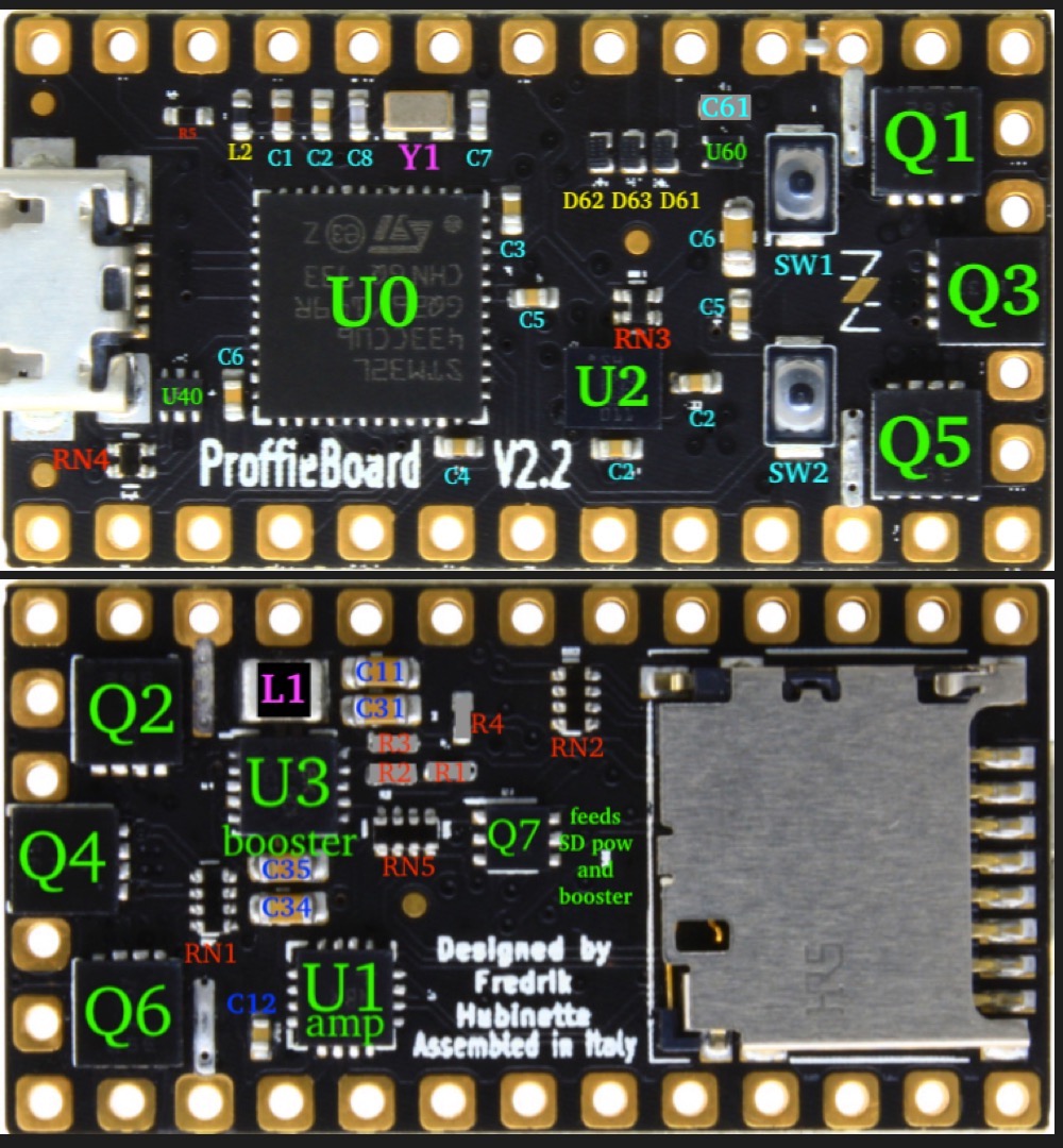
I saw that sometimes power regulation mofsets can burn out, specifically the one in the middle of the board on the ‘underside’ but I looked and mine seems to be fine. From what I can tell there are no burned or melted parts on the board.
I’ve yet to check the battery in Arduino through Proffie is, and I haven’t had the chance to use a multimeter to check voltage from the batt+ and from the 5v pad since I don’t have one.
Any help is appreciated. If I need to replace something on the board I’ll probably just swap the board with a different one and have my local RadioShack replace the part since I don’t have a hot air rework station.
Start with the battery, if +/- looks good, then move to the board and measure GND ↔ BATT+. After that it gets a bit more complicated since we have to start measuring points on the board itself, like the diodes and the voltage dividers and so forth.
I checked the battery +/- and it says 4.25v which seems normal, and GND/+ is also 4.25v. Looks like it isn’t the battery unless I’m reading this wrong.
East side of L1 was very difficult to get a reading due to the small distance between components and large probes, but I was able to get 3.7v which I believe is correct.
South side of R4 is reading ~1.95v which is what the spoken battery level on my saber says as well. I think r4 is bad.
I think you can just put the lead on L1 itself, but I guess it depends on what kind of coil was actually used.
Not really, this would indicate a voltage drop in Q7, which is not really normal.
3.7 volts is still sufficient though, so it may not be a big deal…
No, R4 is part of a voltage divider, and the voltage at this point is supposed to be half of the L1 spot. It’s slightly off, but not too much, so maybe that’s fine too.
However, if your R4 is reading 1.95, the the voltage code is supposed to say 3.9 volts, not 1.95. I think it’s time we take a look at the code and it’s printouts…
If you go to this line:
And add this right before it:
#error If you do not see this error, something is wrong
Ok, so that is super weird, because it means that analogRead() is reading a value of ~1 volt from the “vtest” net (which connects to the south part of R4). It means that the chip and your multimeter are measuring different values at the same point which is weird and unusual.
If there is no other way, you might need to just replace that line I pointed out with just “return 3.7;” this will disable any kind of battery warnings, but if we can’t figure out what’s causing this, that might be what we need to do.
Is it possible this is caused by a bad solder connection?
It’s very bizarre but back when I was running tests on the board and I was having this same problem, I would solder the battery positive to the battery positive pad and the sound would clear up while the board was hot from soldering but would slowly lose voltage and eventually settle back into the low voltage issue I’m having now.
Is it possible that heating the board somehow was bridging a connection somewhere?
A cold solder joint can have a fairly high resistance and could cause problems of this nature. However, I would expect a problem like that to simply go away the first time you heat up the joint. I would not expect it to come back.
I’m going to try what you suggested by the return voltage, I’m hoping that my issue is fixed by this. It’s a donor board from an issue core anyway so in the event something goes horribly wrong I won’t be too upset. I kinda knew that going into this project as it’s 90% reused parts.
Changed the return voltage to 3.7, and there was no noticeable change apart from the board now recognizing it as ~3.7 volts.
After a few minutes of sitting there all of a sudden the audio cleared up, and it sounded normal. Battery voltage reading ~7.5 volts, before going back to sounding terrible after a minute or two. Currently stuck at terrible.
This is super weird, it can’t even decide if it’s broken or not
I think we found the problem. 5v pad is reading ~2.4v with audio playing. Way below 5v.
But it’s weird that it’s stopping and starting working, like the booster is dead but not really? Like it’s broken but just barely able to function for a few minutes if the conditions are right. Is there a way to bypass the booster? Last time I tried to wire to the 5v to the battery+ pad the solder bridge got VERY hot.
Bridging 5v to BATT+ typically works well if the booster is busted.
In your case it sounds like it’s not, or busted sometimes?
I’m wondering if maybe you have a cracked solder joint somewhere.
Cracked solder joints happens when the board flexes sometimes, and they are super hard to see. Cracked solder joints can kind-of-sort-of maintain a connection, but it’s really iffy. Like heat can make it work better (or worse). In most cases, cracked solder joints are easy to fix if you can find them, you just touch it with a soldering iron and it’s fixed.