Wiring for Neopixel accent + PCB

Hello,

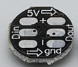
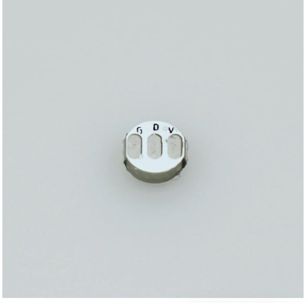
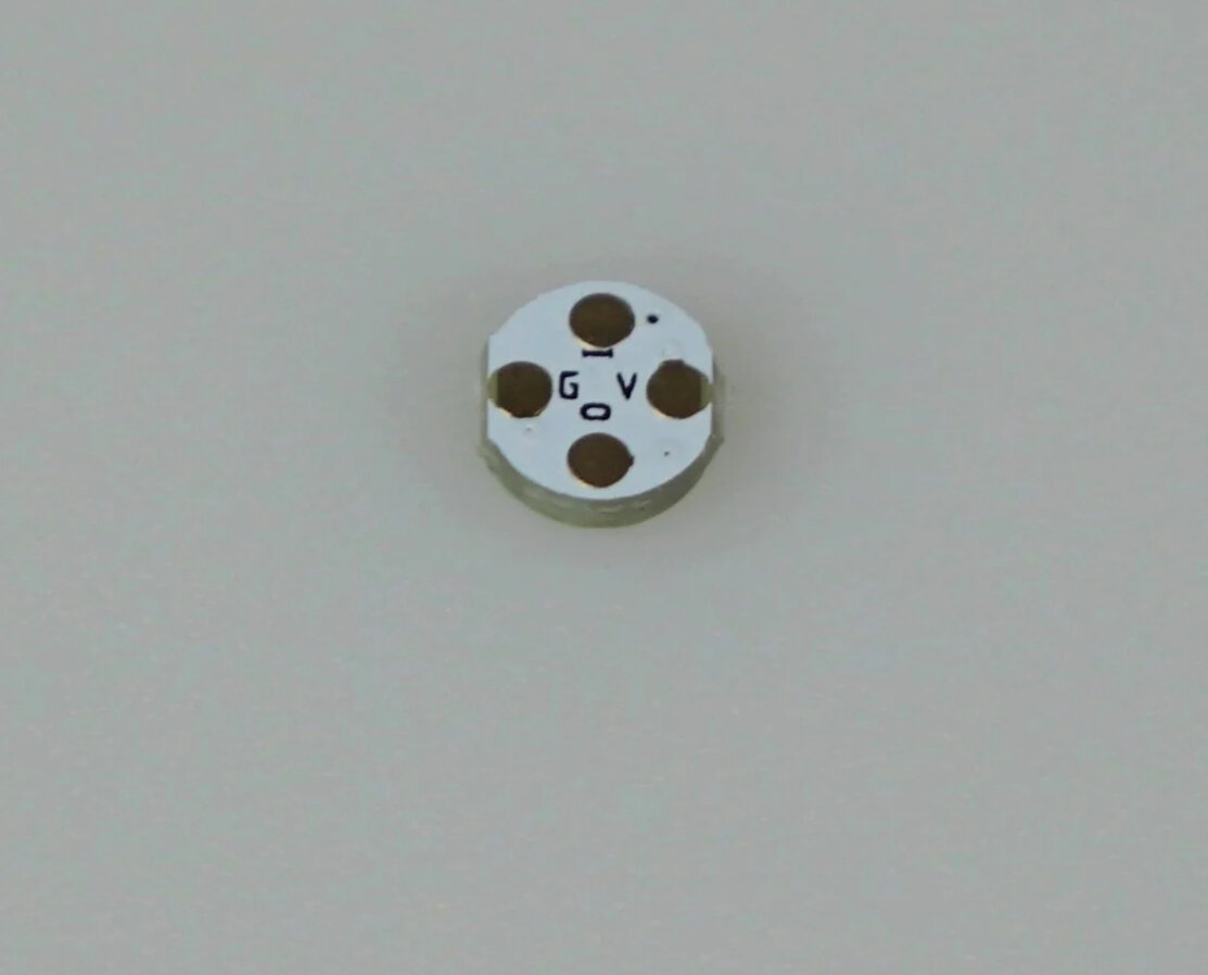
Wanted to see if I could get assistance on how to wire up Goth3D Metal Master Chassis with Proffieboard, including neopixel accent connecting to the bottom of the PCB.

For my configuration, I want to have the accent LED (crystal) behave differently from the main blade. I have it set as ‘blade 2’ with 1 LED. Do I need two data lines for that? One for main blade and one for accent? Or do I only need one data line with the accent wired between the PCB and the board?

My understanding is the two data line options on the PCB are only if you want the PCB to have an independent setup from the main blade, which I’m not interested in (good with version 2). But does the accent need its own unique data line to the board?

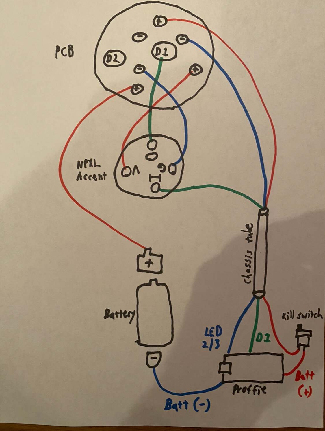
I have two different wiring scenarios below to illustrate, if anyone can look at my overall wiring setup and advise if one or neither would be correct.

FYI The chassis is designed for the wires to go through a narrow tube, to travel through the hilt and connect to the back portion of the chassis, where the board is located.
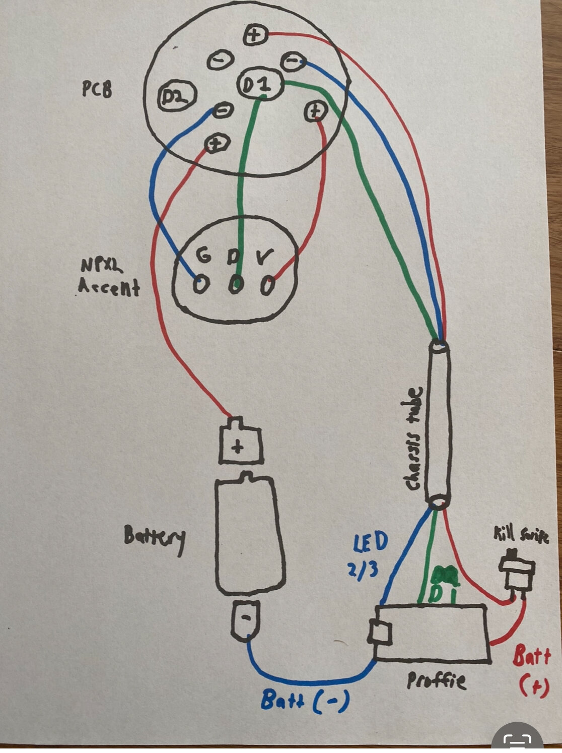
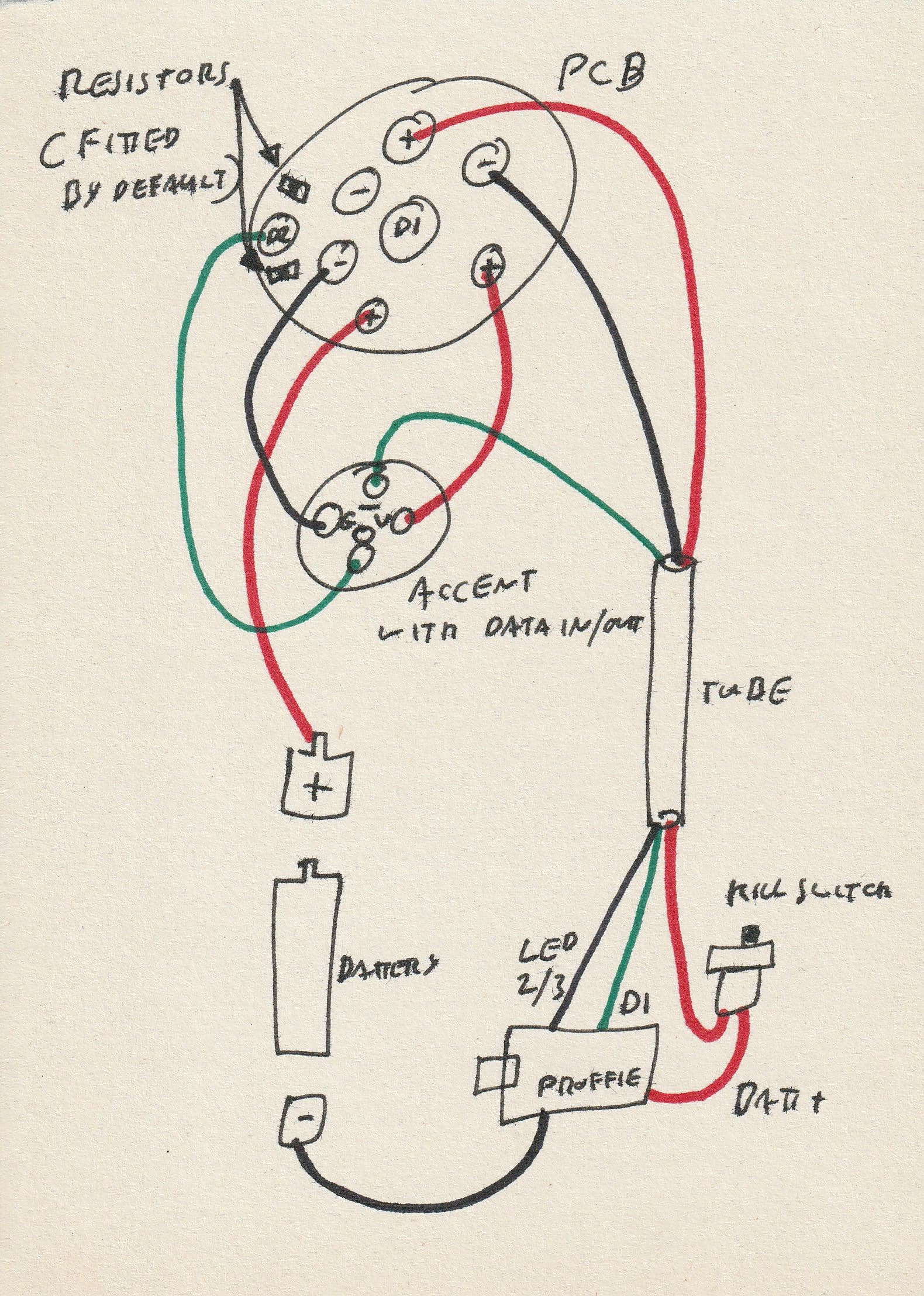
One data line:

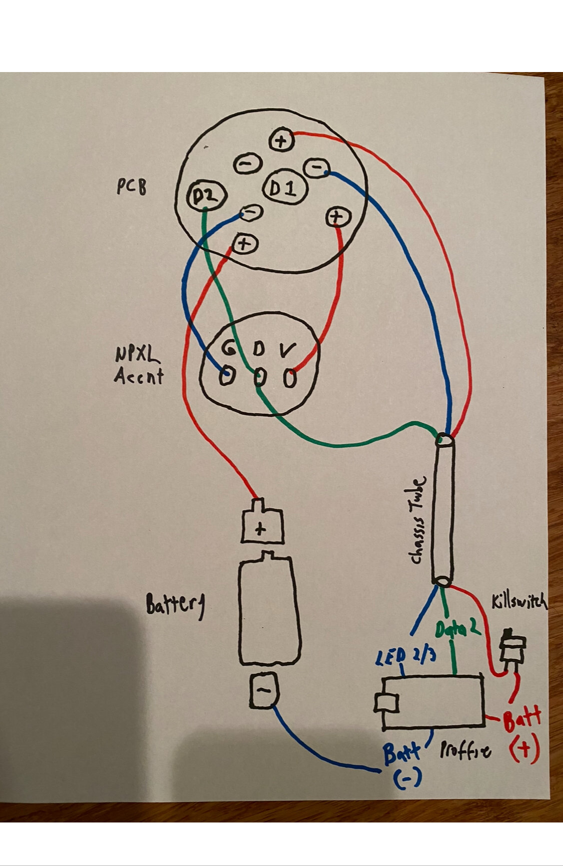
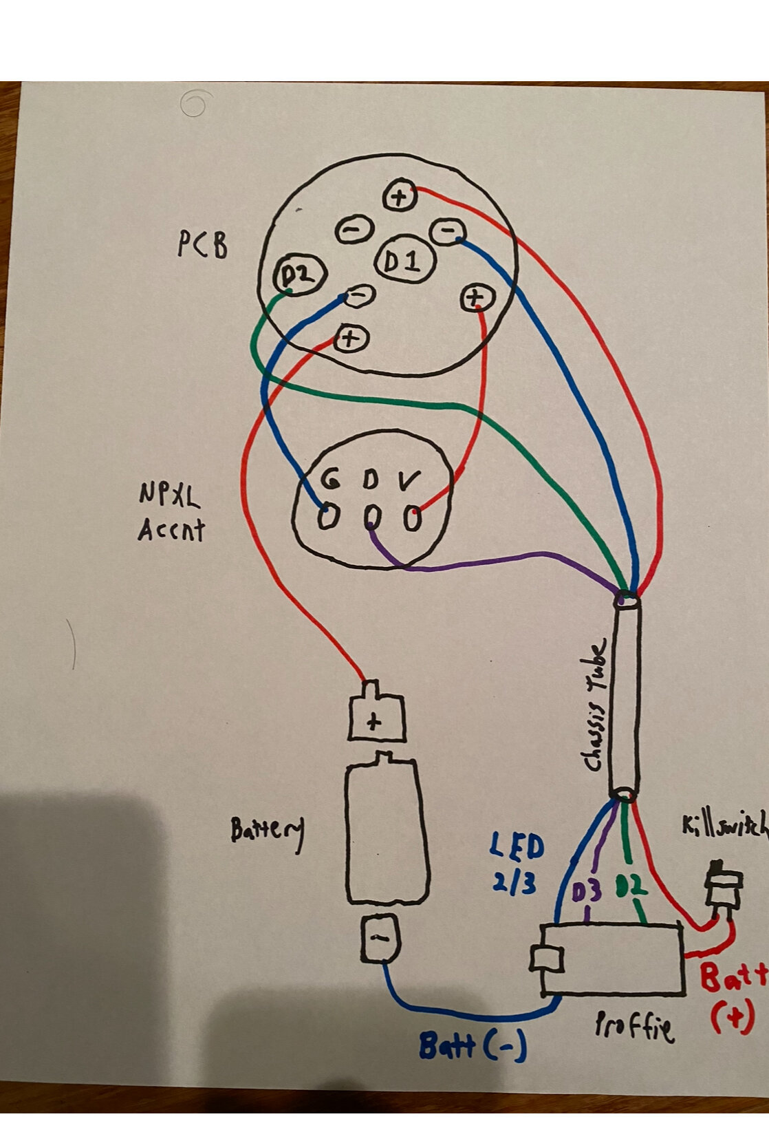
Two data lines; one straight from accent to board:

Thanks

Is the emitter PCB an actual NPXL brand PCB?
If yes, there are options in the manual for how you want to wire it.
If you want to use the crystal LED on the same data line but have separate control over it, you need to have a dataOUT on it so you can pass data serially.
If you wire it like your first picture, the LED will behave the same as the main blade as it’s a parallel connection.
Your 2nd picture is fine, but it’s understandable you want as few wires as possible in that tube.

Yes it’s a V3 NPXL PCB. From what I could tell, the manual covers wiring options depending on how you want the PCB and blade to connect/interact with one another, but it’s not specific on including accents/crystal chamber(s) in addition to the blade. Maybe it’s a little more self explanatory for people who know what they’re doing :sweat_smile: For folks like me there’s a lot of reading between the lines, since the manuals are pretty general for a range of hilt designs :innocent:

This is where my circuitry illiteracy kicks in :sweat_smile: in other words, if I want the accent LED to have its own style and not mimic the blade, I need to have a fourth wire one way or another(?) I’m probably gonna go with my second wiring setup, but hypothetically, where would my connecting point be for the dataOUT in that scenario?

Also just to clarify, I’m not necessarily trying to have a ‘separate control’ over the crystal LED. The edit functions from the blade seem a little too sophisticated for me :sweat_smile: I’m just going with presets that have a different style between the blade and the crystal (if that makes a difference). Specifically, I have Blade 1 (<132 LEDs) and Blade 2 (<1 LED) with unique behaviors configured for each.

Also it seems trickier anyway to wire the data in ‘series’ from PCB > accent > board since it’s such a tiny LED trying to connect so many wires to it.

I actually have another guy helping me who put this same saber/chassis together. But he just has everything mimicking the main blade, so I’m trying to figure out a different setup. He actually advised me to buy a new tube altogether as he did, because the one they include in the kit can barely if at all fit three wires (I certainly wasn’t able to on my attempt). The new one I have can fit four wires; it’s a snug fit but I can fit two 22s and two 30s. Anyways yeah, I think I’ll go with the second option. Thanks again :grin:

The accent LED would have a data in and a data out, like this:

You insert it inline between the board and the NPXL PCB like
Board → data in → data out → NPXL PCB

Then you write the BladeConfig definition for those ‘blades’ to use SubBlade, like

  SubBlade(1, 132, WS281XBladePtr<133, bladePin, Color8::GRB, PowerPINS<bladePowerPin2, bladePowerPin3> >()),
  SubBlade(0, 0, NULL),

That says the data will come out of the data1 pad on the Proffieboard, and start by going through 1 pixel (address 0 which is the first pixel. LEDs are counted with an offset of -1)
then go through 132 more pixels.
It will assign your first blade style in the preset to the first entry in the blades array, so in this case the main blade.
The second blade style will drive your accent single pixel.

note* your drawing has you using data 2 on the board, so if that’s what you want to do, then you would write blade2Pin instead of data 1 on bladePin.

Just because the NPXL says D2 doesn’t mean you need to use data 2 on the board.
THat’s there just because you can wire it the same way internally on the PCB (to be in series, parallel, or separate data lines each to D1 and D2.)

That’s what I meant by ‘separate control’, as in giving it it’s own style as opposed to mirroring the main blade’s style.

Ok… mine looks like this - I’m guessing you’re not supposed to solder two wires to one pad… and my first diagram is infeasible without a dataOUT pad. The other guy I’m working with who has his accent mimicking the blade, assuming he has the same accent as mine, would he have done it by connecting his accent to D1/D2 on the PCB, and the other data pad on the PCB would have had a line to the board?

I know he used a subblade configuration, but I think he did some tweaking to it outside of what the configuration generator provided by default

Circling back on this, I ordered a new accent with the DataIN / DataOUT pads (pic below):

With this new accent, would below be the correct way to wire these pieces together? Bear in mind this chassis requires minimal wiring to go through the narrow tube, hence why connections need to be made between the accent/PCB at the top of the chassis (manual for reference: https://goth-3designs.com/instructions/diy-kr-master-qgj-2023-master-chassis/ ):

I’m guessing if I wanted to have two different styles for the accent and main blade off one data line, I need to code the sub-blade first in the sequence, since the data first flows into the accent, then followed by the main blade as the second blade, since it flows from DataOUT to the PCB.

If that’s accurate, could someone assist with providing that code? I doubt that’s something that would be generated from the default selections in the Proffieboard configuration tool.

When I spoke with Khal about this, he said the GND points of the accent are not meant to be connected to the PCB if I plan to run it independently. I’m not sure if that meant it’s impossible for the accent to have a separate style unless its +´s/-‘s are connected independently to the soundboard. If that’s accurate, could it be the case that this build is not capable of independent styles, due to the restrictions in the wiring setup?

Yep, your diagram will work fine, and as you say, you’ll need to set your blade array as sub-blades.

I think what Khal meant is that you can’t run thin cables to the accent pixel, then thicker ones from the pixel to the main blade, as the thin wires will serve as a current bottleneck. But your diagram will work fine. You can run heavier wires to the main blade, then thinner ones from the main blade to the pixel as you’ve drawn, then one data line to run both as sub-blades.

You’ll need to add this line to the defines at the top of your config:

#define SHARED_POWER_PINS

And at the bottom of your config in the blade array, your sub blade setup will need to look something like this:

//  Main Blade:
    SubBlade (1, 132, WS281XBladePtr<133, bladePin, Color8::GRB, PowerPINS<bladePowerPin2, bladePowerPin3> >()),
//  Accent Pixel:
    SubBlade(0, 0, NULL), 

This assumes your main blade will have 132 pixels in it, so the important numbers in the blade array are the 133 which tells the Proffie how many pixels are in the total array. Then the first two numbers (1,132 and 0,0) tell the Proffie which pixels to treat as a separate ‘blade’. Note that in terms of identifying the pixels, the count starts at zero, so you offset the numbers by one. So numbers 1 to 132 will be from the first pixel to the last pixel on the main blade, and the zero to zero is the single pixel on the accent.

After that you need to add two separate blade styles per preset. So your config might look something like this:

#ifdef CONFIG_PRESETS
Preset presets[] = {
   { "TeensySF", "tracks/venus.wav",
//  Main Blade:
StylePtr<InOutHelper<SimpleClash<Lockup<Blast<Blue,White>,AudioFlicker<Blue,White>>,White>,300,800>>(),
//  Accent Pixel:
StylePtr<InOutHelper<SimpleClash<Lockup<Blast<Blue,White>,AudioFlicker<Blue,White>>,White>,300,800,Pulsing<Blue,Black,2500>>>(),
"blue"},

This will give you a blue blade with the accent pixel pulsing between blue and off slowly when the main blade is switched off. Then when you switch the main blade on, the pixel will follow the blade until you switch it off again.

Hope that all made sense.
:slight_smile:

1 Like

And I’ve just realised that NoSloppy had already covered some of this, so apologies for the repetition. But at least having it explained twice in different ways might help clarify. :slight_smile:

Thanks - that said, I was told I can make this work with the accent I currently have that’s GDV, and I’m thinking I’ll move forward with that :sweat_smile:

That said, with this revised diagram would it work more or less the same?

It would work but not as a sub blade, and you wouldn’t have separate control over the accent…

The output from the data on the main blade pcb isn’t a true output. All you’re doing in this diagram is effectively splitting the data line so that main blade and accent both use the same line. Under this setup there’s no need for sub blades or second blade styles - the accent will just follow the main blade. There’s nothing wrong with that, but it means you won;t be able to programme separate effects like having the accent pulse with the main blade off.

One last thing - if your blade connector is a Shtok connector (which I assume from the D1, D2 references it is) and you wire to the back of the central pin as per your diagram, the blade itself will work fine when you fit it in the hilt, but the LEDs on your blade connector pcb won’t work at all.

If you wire it like this (sorry, I didn’t have a blue pen to hand), using the second pixel you bought and the subblade settings that NoSloppy and I suggested, and checking that the blade PCB has the two resistors fitted (which they usually do by default) then everything should just work. :slight_smile:

Thanks for the help :slightly_smiling_face: - I had actually decided to just move forward with the accent that I had. If the unique behavior worked with subblade settings great, if not I’d just go with blade imitation, but I just wanted to get it done.

Buuuut I ended up frying my Proffieboard, likely from when I attempted to light the blade manually by pressing the PCB to the blade… so now I have a new Proffieboard coming in the mail this week along with a new accent.

Suppose I’ll take the opportunity to use the new accent when I wire the new Proffieboard :roll_eyes:

Quick question on your diagram - I see it goes from D1 on the board > DataIN on the accent, then DataOUT to D2 on the NPXL PCB. Is that accurate or would it go from DataOUT > D1?

Also if there’s any chance you could send the full subblade config from ‘BladeConfig’ to ‘#endif’ that’d be awesome. I don’t trust myself fine tuning the code :sweat_smile:

The diagram is correct, i.e. the last data wire has to go to D2 on the neopixel blade connector. If you wire it to D1 on the blade connector, the main blade will work, but the LEDs on the blade connector itself won’t. This assumes those two small resistors are fitted. If not, let us know which resistors are fitted, if any, and we can adjust accordingly.

And here’s the code:

BladeConfig blades[] = {
  { 0,
//  Main Blade:
    SubBlade (1, 132, WS281XBladePtr<133, bladePin, Color8::GRB, PowerPINS<bladePowerPin2, bladePowerPin3> >()),
//  Accent Pixel:
    SubBlade(0, 0, NULL), 
CONFIGARRAY(presets) },
};
#endif
1 Like

Thanks :pray:t3: - So even though I would be using the D2 pad on the PCB, I wouldn’t need a corresponding connection to D2 on the board?

And yes, the PCB has the default 2 resistors

No, the D references are just to distinguish multiple pads on those components. They are nothing to do with each other as such. You can use any data pad on the Proffie as long as you tell it in the code which one you’ve used. In this case we’ve used Data 1 which we’ve described in the code I posted as ‘bladePin’. If we’d used Data 2 on the Proffie, we would change ‘bladePin’ to 'blade2Pin; if we’d used Data 3, ‘blade3Pin’ etc.

1 Like

Thanks so much :grin: on a slightly separate note… since I basically fried my board from mishandling the pins on the blade… suppose I set the accent/crystal with an off-behavior for a set idle time… if I was to try removing the main blade while I have it powered down but the accent is still blinking off the accent connected to the PCB, could that potentially cause a short?

I assume not since probably nobody would use a setting like that in such a case… but I would be manually tampering with the blade while power is still going to the connector… so I just want to quell my paranoia.

If you’re asking whether it’s worth trying to hold the blade and the connector against each other by hand again, even if the blade isn’t lit, the answer is still no.

In this case it’s super-no, because your setup is using shared power pins. This means that while either the blade or the crystal is active, power will be going to both, even though one of them might not be lit.

Basically if you tell the proffie to light/pulse or whatever the crystal, it will make the crystal positive and negative live. Since you’re using shared power pins, this means the main blade positive and negative will also be live, but the blade won’t be lit because it is awaiting an instruction from the data line to light it.

But if you’re asking can you fit the blade into the hilt while the crystal chamber is on, then yes you can, but only once everything is built and finished and the hilt emitter itself keeps everything properly aligned. In other words, if the hilt is finished, it should be impossible to misalign the blade against the connector.

Thanks :grin: Yes what I meant was, when everything is fully assembled, is it safe to add/remove the blade if the ‘crystal’ is still pulsing, even though the PCB itself is not lit up.

Reason I ask is because this is probably a more unique situation for this particular lightsaber hilt, since it’s +/- connections are directly attached to the PCB, whereas most would have their own separate connections to the board.

I assumed it was generally safer to add/remove the main blade to/from the fully assembled hilt while the PCB is powered down, then switch the power on only after the main blade is securely fastened to/removed from the hilt. But to your point, it shouldn’t matter once fully assembled, because it would be impossible to misalign the blade/connector.