Everything should be safe once fully assembled, because there should be no possibility of pogo pins touching other that they aren’t supposed to touch.
1 Like
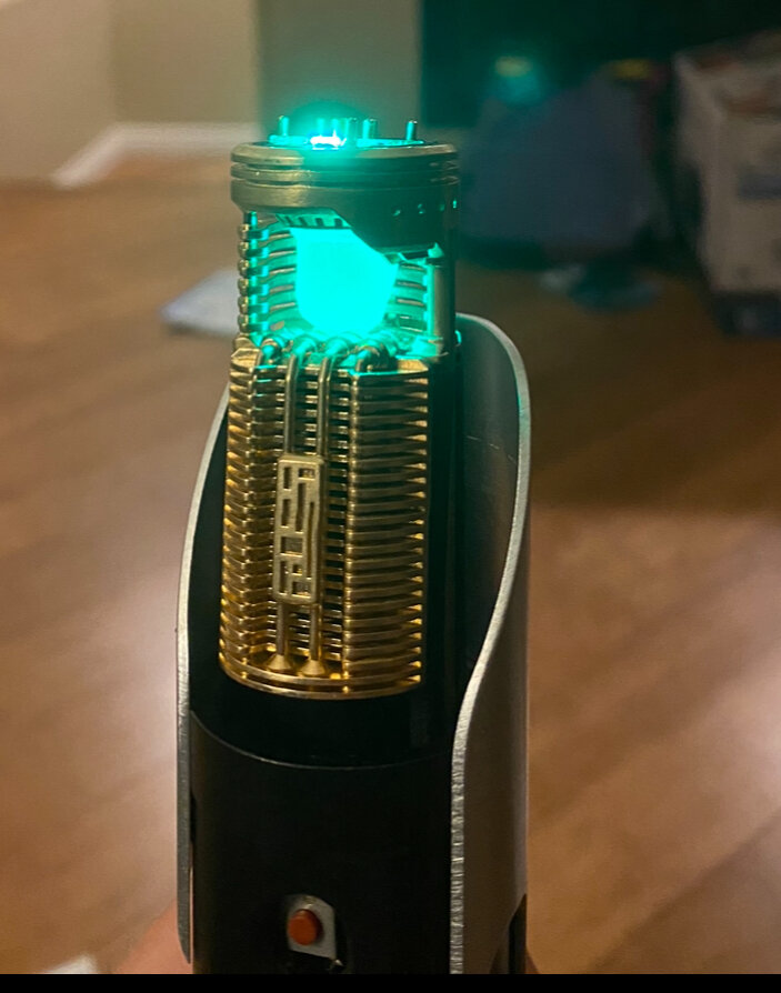
Hello - So I got my saber up and running - hooray ![]()

Buuuut due to technical difficulties I wasn’t able to use the accent with the dIN/dOUT connections. Actually I had to switch out my entire replacement PCB with the one I previously set up, with the -/d/+ accent.
Still used the below code. Works as mentioned. Predictably though, without the proper sequence, the ‘crystal’ setting is applying to both the accent and the first LED on the PCB.
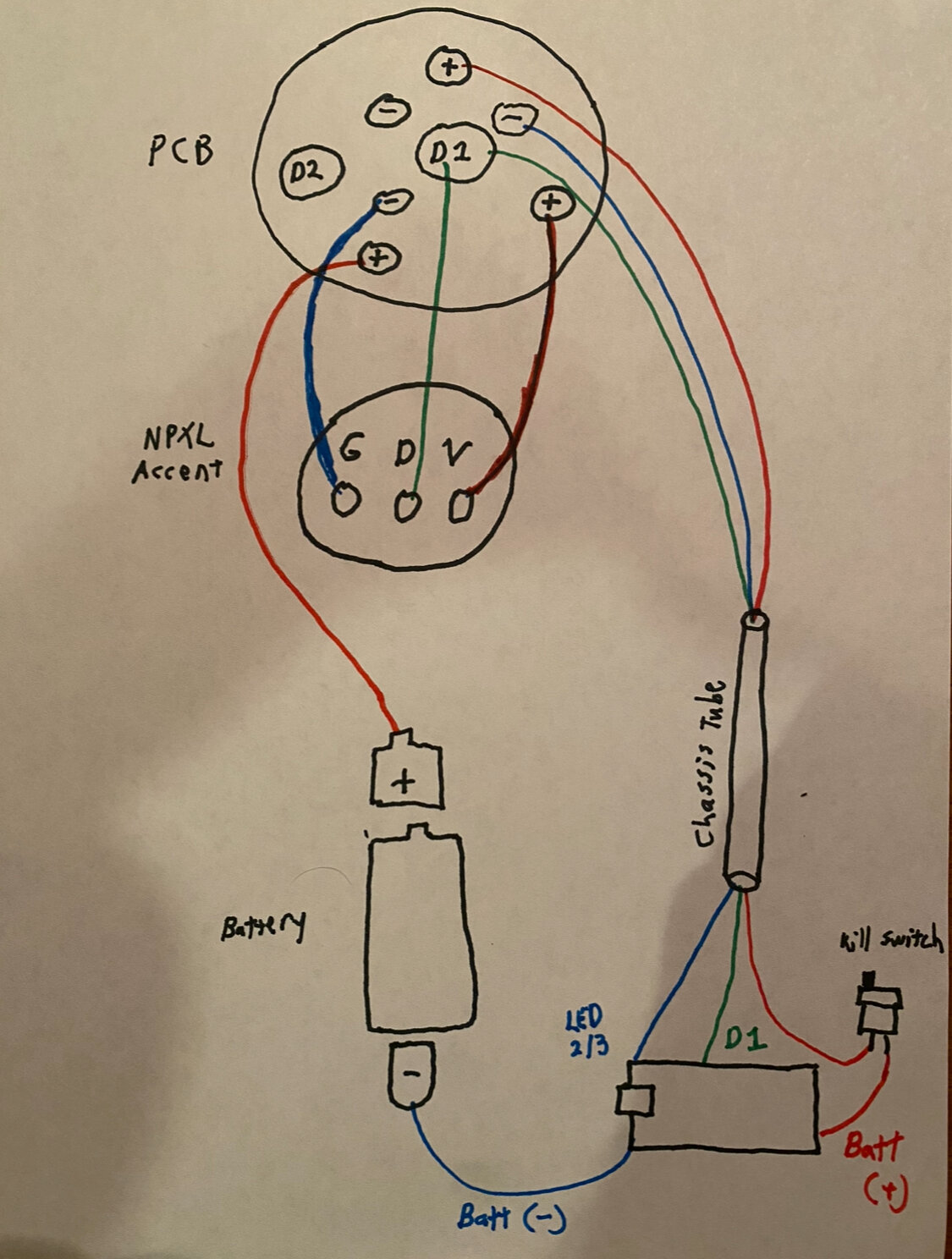
I know it’s a long shot, but wanted to check again if there is an initial code format like above that will allow so only the accent has the effect but not the PCB, even though they’re on same data line. To recap, I have it wired like below. Thanks again ![]()
As far as I know, there isn’t a way to have different effects on two LEDs sharing the same data input - you can only do it with sub-blades and only if the LEDs can be properly daisy chained with proper data outputs.
The weird thing about your install is why the first LED on the pcb is lit - by rights, if you’ve wired the data to D1 on the pcb (i.e. the back of the centre pin itself) none of the pcb LEDs should be lit. Are you sure you didn’t wire it to D2, as that would have the effect seen in the photo.
Yeah I’m pretty sure I wired the data to D1 center pad on the PCB, then connected to D1 on the board. I thought it didn’t matter whether D1 or D2 on the PCB is used to connect to the board, as long as the code corresponds correctly to whichever Data pad is used on the board(?)
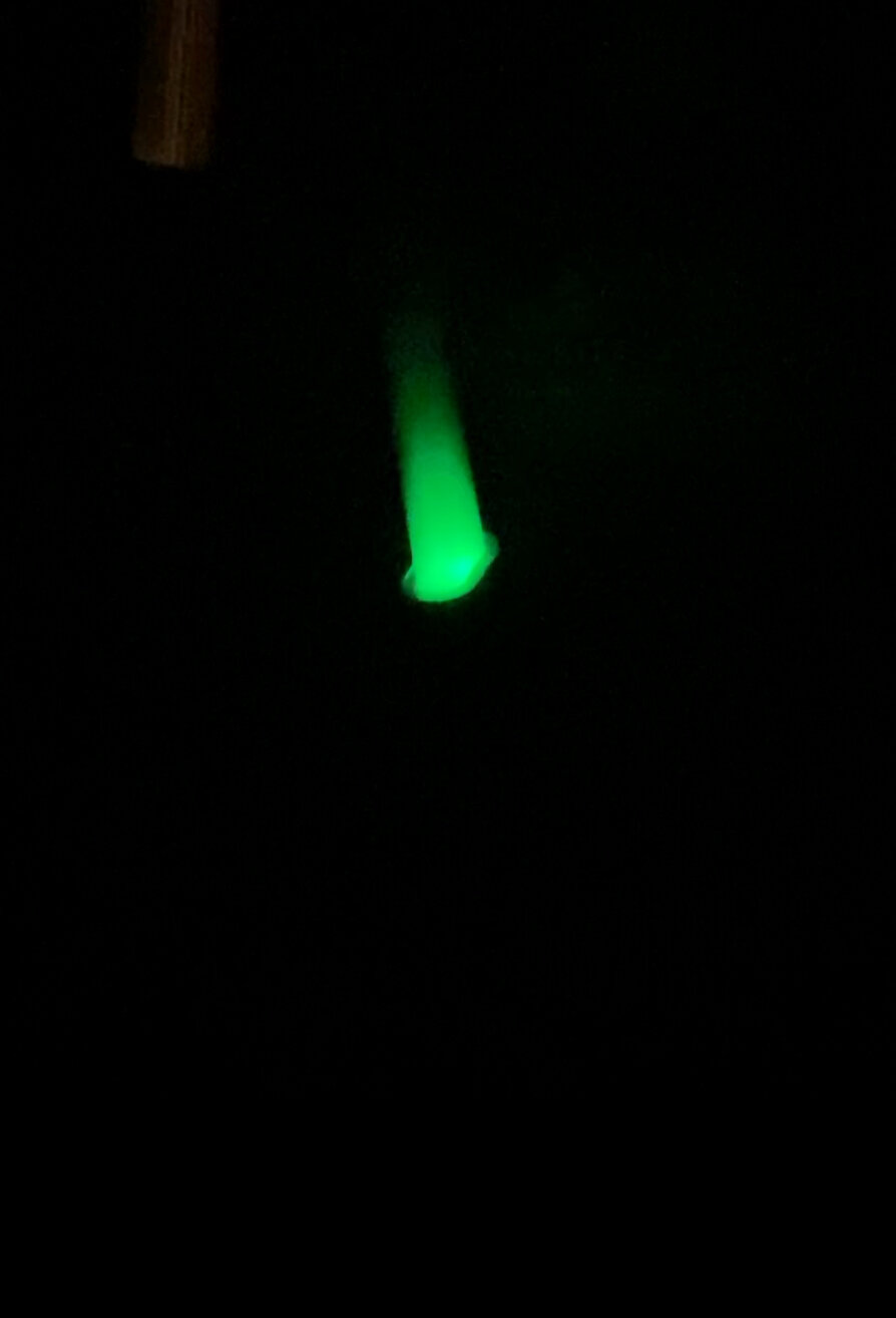
Also to add a bit more clarity (if it matters) that single LED lightup on the PCB translates to the main blade when connected, so it has below effect (goes away after 2 min idle time per my setting). Unless it’s an emitter effect I unknowingly applied in the settings but pretty sure that’s not the case ![]() Kinda serves as a visual supplement to navigating the presets
Kinda serves as a visual supplement to navigating the presets ![]()
I think with that hilt PCB, by default, if you wire to d1 you get the hilt LEDs in parallel with the blade. If you want d1 to only pass through to the blade, you have to remove one of the resistors. See TheManual.
It’s an impossible shot.
There is no way to have two pixels wired in parallel do different things.
(Although, you could potentially turn off the power to one or the other, thus have it not show anything, but that still requires separate power wires.)
Yep I figured as much - I cut my losses and took away the Off Effect.
I still gave the crystal separate behavior from the main blade while activated (fast pulse). I assume that behavior is also on one of the LEDs of the main blade, but it’s not noticeable, and probably on one of the LEDS that are inside the hilt and not visible ![]()