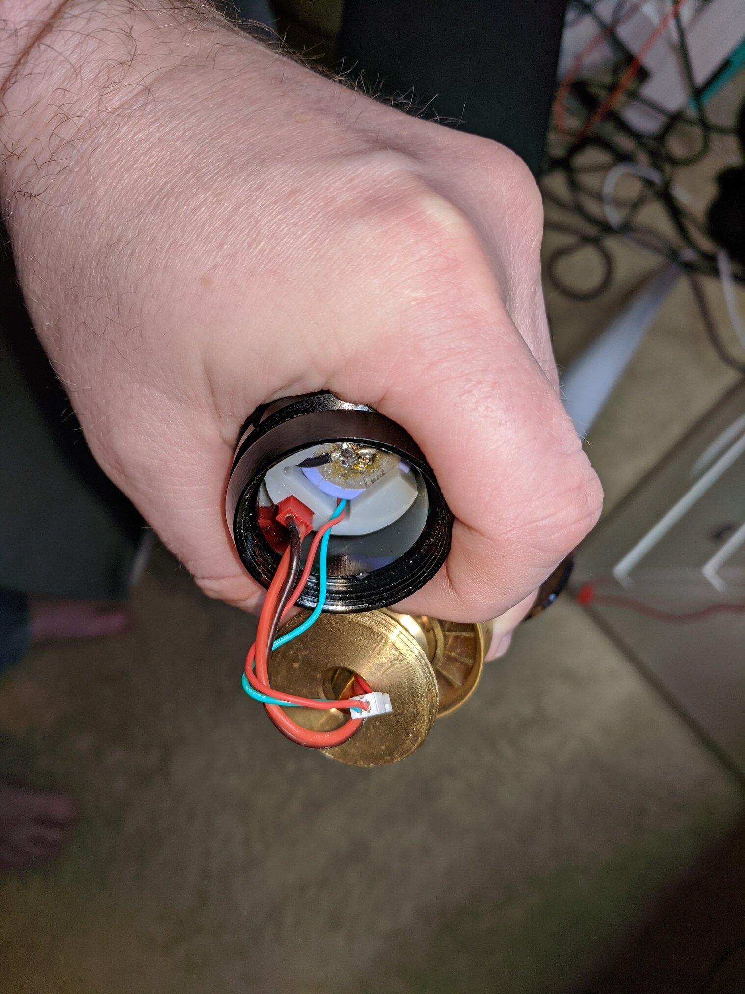
I have a MoM install for a customer and am after some general tips on the best way to manage wires between the emitter PCB and the blade side PCB housed at the top of the grenade section.
In my mind I’m visualising not a lot of space to tuck away excess wire.
Would love some input/photos/advice 
This might be helpful:
thin_neck.pdf (386.4 KB)
2 Likes
The chassis has a slot in the bottom for the male JST connector.
https://fredrik.hubbe.net/lightsaber/k4/chassis3.html
1 Like
This is a great infographic, thanks!
1 Like
I wired the emitter/grenade pixel PCBs with as short a wire as I could, then split open the windvane section of my Creepy Uncle and shortened the wires there by splicing.
1 Like
I have an 89Sabers K4v2 on the mail, and have exactly this problem. I want to address only the emitter LEDs in parallel to the blade, and I want to still have the Blade Present function (plus BladeID). The problem is that I think I will need a 5 conductor connector for that.
That should be 4 total, but there are these 
1 Like
Thanks mate. Sounds like wiring the grenade section PCB first is the way, then feed wires through the neck to emitter and wire up that PCB 
Thanks for taking the time to answer 
1 Like
I had already bought those, waiting for them.
What I don’t get is the number of contacts. If I want NPXL with the connector in parallel and Blade Present, I need +, -, data1, data2 and BP. Or I’m not understanding how BladePresent works.
If the PCB LEDs are just parallel with the main blade they’d share Data1.
Blade Present (aka detect) just needs to be a floating pin until the blade side PCB pulls it high or low because the rest of the ring is in contact with the connected pogos. If that makes sense.
Yes, I was not explaining myself correctly. I wanted to be able to treat the PCB neopixels as a different blade. Thus the need for a Data2. And, of course, I need a line to Blade Present so it can get pulled when a blade is inserted. Thus the 5 contacts.
If it’s a standard, non-eco NPXL, it provides for a series connection.
Use SubBlade and one data line can feed both the onboard and main blade LEDs as discrete blades.
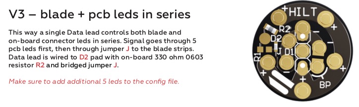
You’d then ignore the “add 5 pixels” line in red, as they’d be addressed as their own entity.
It’s a V3, which comes configured in parallel. I assume I would have to desolder R1, put a dip of solder in J, and connect Data1 to D2. I’ve never done the SubBlade. Can I get Blade Present and Blade ID on the blades and sill handle the 16 LEDs on the PCB when the Blade is removed?
Thanks for your patience.
Connectiing PCB and blade in series will make blade ID not work.
1 Like
Exactly what I suspected. So I will have to use a 5 pole connector. Which is no problem at all. I should be recieving a few of these in a couple of days:
Those have 6 poles, so I should be fine, right?
1 Like
Wait, what? Why would it not work in series?
Is there any other way to detect whether the blade is present and prevent the connector LEDs from illuminating without using a second data connection?
Not that that I can think of.
Is leaving the PCB on when there’s a blade inserted a problem?
Just that it’s 16 LEDs drawing that much extra power from the battery. Might be better not to have them at all.