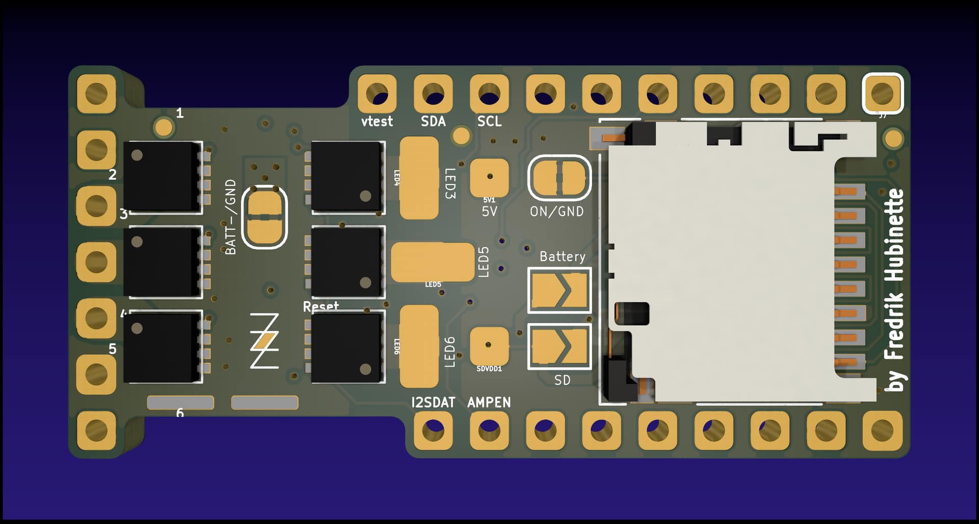
Ok, so I just finished routing a TeensySaber V4 board.
Unlike the Proffieboard V3 and M2, there is no reason for this one to remain hypothetical. I’ll try to post some pictures tomorrow, but this ain’t your grandpa’s TeensySaber, here’s what’s on the board:
Mates with a Teensy 4.0
Uses contact springs to access the SD card pads on the bottom of the Teensy, which should give us super-high SD card speeds. (UHS-I), and leave more pads available for other stuff.
Just about everything on the board is optional and can be dropped if you want to keep things simple.
Spaces for both MPU-6050 AND LSM6DSM (although I wouldn’t expect anybody to use both, it’s just to make it easier to find components.)
Low-current cutoff circuit. (no need for a high-current switch.)
Reverse polarity protection.
USB charging
Space for 6 FETs on the bottom. (3 with through-hole connectors, 3 with flat pads.)
Same Booster & Amplifier as V2 proffieboards.
PCB design follows Oshpark 4-layer rules.
It still needs a lot of cleanup before it’s done though.
I might also go through and replace the 0402 components with 0603 components to make it more DIY-friendly.
And of course, all of this is completely untested so far.
Not sure if I’m going to try to make and sell these though, or if it’s just for DIY yet, as I haven’t quite figured out how I’m going to test them yet.
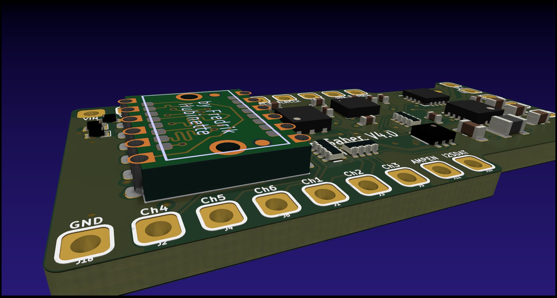
Got the spring contacts from digikey. They are really really tiny.
I don’t think regular pin headers will work, because the boards will need to be really really close.
In fact, I suspect that if the capacitors on the bottom of the teensy touch the components on the TeensySaberV4, the boards might still be too far apart…
But how?
A board like that has no space for components on it.
Having the components off to the side (like the rows of pins on the breakout board) would make it huge. And I can’t figure out a way to layer another board on top of that one to make it work the way I want to.
Exciting! I’ve been playing around with teensysaber v4 ideas myself (but I have no clue what I’m doing, very new to circuit design).
This solves the CPU problem (since teensy 4.x seem to be fine stock-wise), but what about the IMU stock? LSM6DSM seems OOS at the usual places, while MPU6050 is worse and is discontinued. Would the former be drop-in compatible with other LSM6DS* chips (like the LSM6DS3TR-C and LSM6DSLTR)?
I selfishly would love it if I could order from a service like jlcpcb (or other SMD assembly), though if you do start selling I’d definitely consider getting some direct.
Also, for spring contacts are you using typical pogo ones? I’ve seen them come in a ton of different heights, maybe taller ones would give more clearance.
There are a number of LSM6DS* IMUs that might work, although none of them are easy to find right now.
However, if the MPU6050 is discontinued, maybe I should find a chip that is available and create a spot for that instead.
Assuming I can make this work, I will definitely publish the designs so that you can order bare boards from any PCB house you prefer.
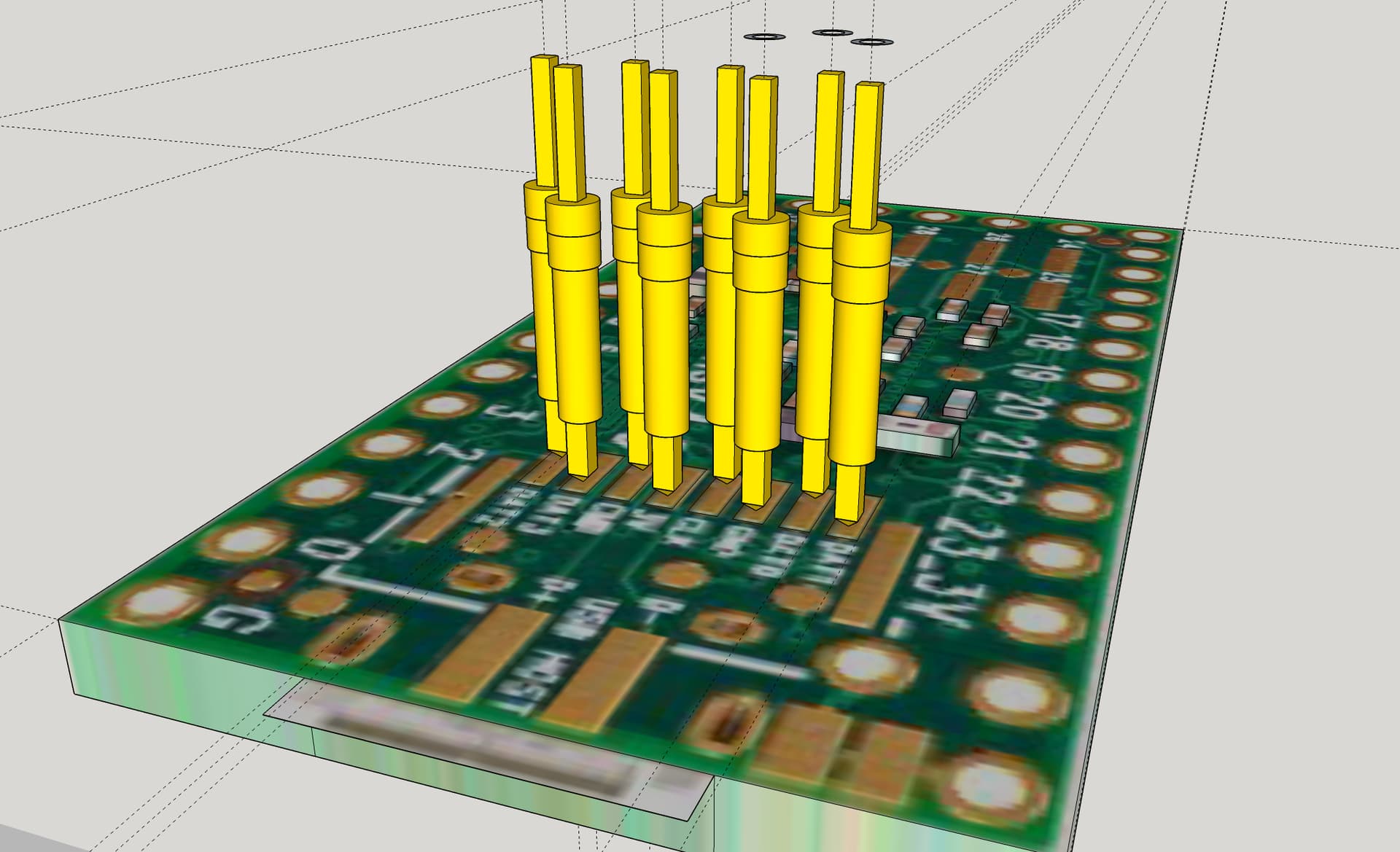
The spring contacts I was planning to use are fairly specialized:
They come in 0.4mm or 0.8mm heights. The 0.8mm ones can make a connection up to 1.7mm away. Standard header pins are 2.54mm, and while there are thinner ones, I would quickly run into problems because the components of the TeensySaber board would be touching the components on the bottom of the teensy. 2mm is as close as they can get without touching.
So, that means one of two things:
I have to put the components on the TeensySaber in positions where they won’t hit the components on the teensy. That to me is a bit of a nightmare scenario, so hopefully I don’t have to do that.
I need taller springs.
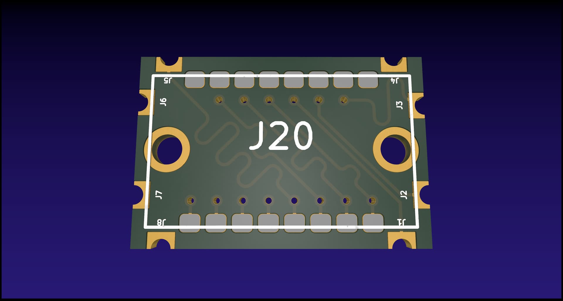
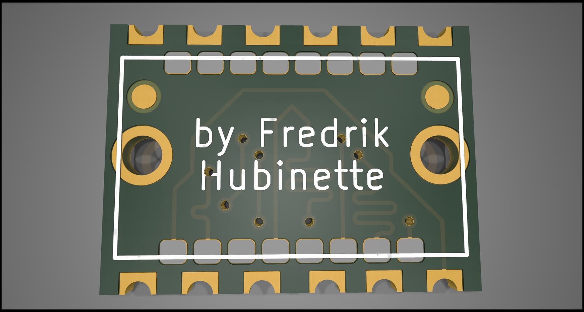
Since I haven’t found taller springs, I’m thinking of trying a hack: Put the springs on another PCB, then solder that PCB to the teensysaber. That would add another 1.6mm to the springs. 2.54 - 1.6 = 0.94mm, which is would work.
It’s not great assembly-wise, so if someone finds a better solution, let me know.
This kind of what I was getting at earlier, except I would make a mini castellated board to connect the two boards, so you are not forced to find parts the match the exact spacing of the teensy 4’s pads. I have not yet figure out the details. I guess you are much further along then I thought.
The problem is that I can attach the mini board to one side, or the other side, but not both. And even if I could, there would be no way to test, check or fix the results.
You are right it does not make sense to sandwich the boards directly. I was thinking, I would design a mini castellated board that aligns to pads on the teensy 4. The mini board would have 100mil surface mount pads for something like:
I plan to use a two perfboard, one with headers and the other without to align the header while soldering. This would make everything spaced at 100 mils, but it may take too much space for your design. Anyways, I plan to try it once I get some time.
Interestingly, it looks like TDKs new motion chips are pin-compatible with LSM6DS*. It’s only too bad the LGA-14 format is a bit fiddly for DIY.
Bye bye MPU6050 footprint.
Hmm, I think the pads along the short edges are ending up too close to the solder pads on the teensysaber. Fortunately, getting rid of the MPU6050 means that I have some space on the board, so I can make the springboard a little wider and put all the pads on the sides.
Another idea - super tiny POGO pins offset from each other. I can’t find any 1mm pitch pogo pins (most seem to be 1.83mm wide), but there are some extra small that only have 1.09mm pads. If you offset those about 1mm front to back you can fit them.
(these are mill max 0950, discontinued but there’s a direct replacement available). I haven’t used these and don’t know if it would work for sure, but in theory the measurements seem to work out. 1mm between the front/back rows. 2mm between each left/right pin. The teensy pads are about 2mm, so each pogo pin would be about 0.5mm from the closest edge. Pins use 0.18" through-holes (~.5mm?), which should still be doable for PCB manufacturing. Pogo pin pads would be about 0.657mm apart (diagonally), so space should be ok.
Might be easier to source & solder vs. the special spring block + secondary castellated PCB?
Have you thought about an offset on the board and using the sd card connector? It would add some length but not so much that it would be longer than some boards.
Here is one i found. Thought about testing it for some other projects.