TeensySaber V4

It’s a possibility I suppose.
It would make it possible to use those pogo pins, but I’m not sure it’s worth it since:

  1. boards would be further apart (which takes up more space)
  2. sd card would stick out, making it longer (which would take up more space)
  3. That sd card holder looks like it would hold the sd card less securely, which could be a problem.
  4. The mill-max pogo pins are 40-80 cents each, which I think is more expensive than my solution.

For now I would consider this the backup plan.

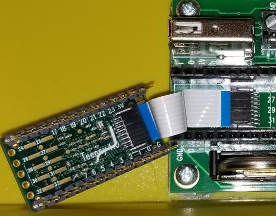
Other possibilities include using flexible PCBs or a flex-cable with connectors to connect the two boards. The footprint on the teensy4 was meant for a flex-cable connector after all.

1 Like

Its a cable connect like in the pic you posted. the upside to the flex cable is it would allow the boards to be closer than if using pogo pins. thus allowing a thinner profile. Also it might allow use of spring pins on the pads for pins 24 to 33, meaning more pins for other uses.
Now I just need to find my teensy 4s I have. Seem to have misplaced the box my teensy 4 project was in.

Got something in the mail today:

3 Likes

Slick! Those wiggly traces, are those for constant-timing or something else?

1 Like

I am a fan of the flex cable as thats the design

1 Like

Feel free to design one with flex cables. :slight_smile:

1 Like

Yes, the squiggles are there to make all the traces the same length. With 50Mhz+ signals, that sort of thing can matter a lot.

1 Like

Here it is on the teensysaber board:

4 Likes

Well I am using a 4.1 for one of my projects. So no need for the proton pack. But if proffie remain high. I may do a teensy saber 4 for one or 2.

So I will probably redo this board. for the 4.1 once everything is worked out.

Looking really good. I can’t wait until I can get my hands on one.

Which IMU are you planning to use? Would this one work: LSM6DSO32TR STMicroelectronics | Mouser

That one is a little tricky. It’s mostly compatible, but the range selection register is not.
I’m not sure if there is an easy way for ProffieOS to detect this and adapt or not, but as the code is written right now, it won’t work well.

Prof,
The board looks sweet. Cant wait to get my hands on one when they are done.

lol, will do if I can find the connector. but still looks good.

First prototype is shaping up. (apologies for the fuzzy picture)

Still need to figure out a way to test these though…

1 Like

Looking really good!! Excellent Job on the design. Any idea on the timeline for availability?

The hard part is going to be to build a testing machine for it.
I don’t have anything like a timeline yet.

1 Like

How are things progressing with the testing machine for the TeensySaber V4. Can’t wait to see the results and try one out. Most of all thank you for all the hard work you have put into the TeensySaber version and the Proffie boards.

It’s been slow going. Not only is it’s tricky to get the test probes in the right place, but I also haven’t had that much time to work on it lately.

i know it’s been a while, but has there been any updates for the teensysaberv4?