Teensy Prop Shield Build

following, as Im doing the same thing, started based on I Like to Make stuff video as well.
If I should make a new thread, i can do that, but I figured if we’re in the same boat, it might be relevant.
I have the:
Teensy 3.2,
prop shield,
power booster (per the v1 directions)
FETS
SD Card Adapter
Speaker
recharge port
2 momentary buttons (non LED, nothing fancy yet)
18650 3.7v battery and small holder that fits easily in hilt
and pair of 144 Neopixel strips, i plan to shorten to a 32" blade visible (total 34" i figure)

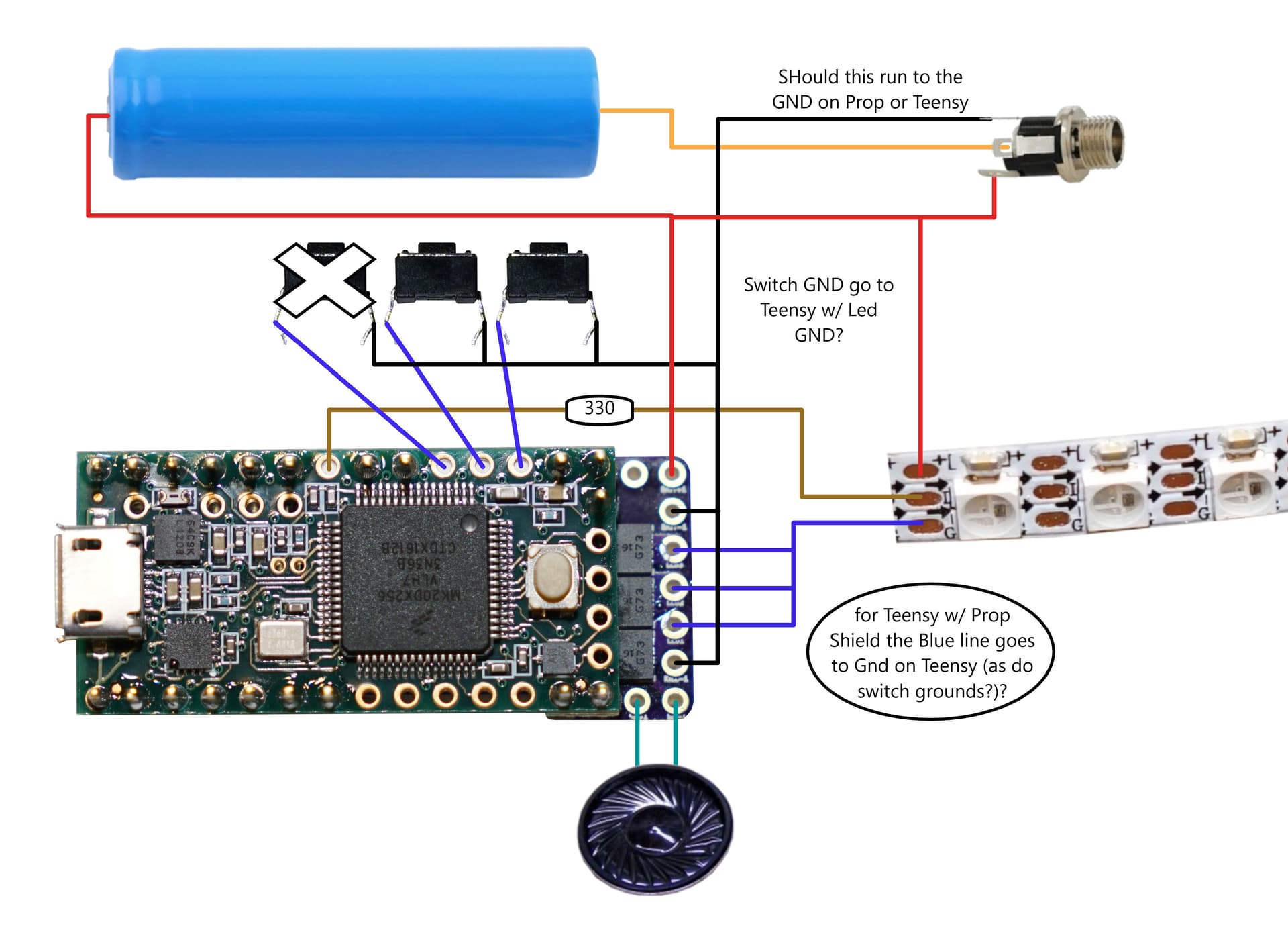
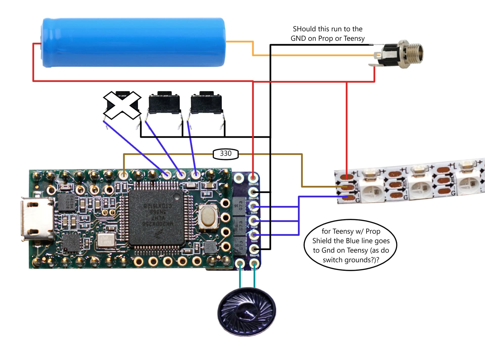
I’m confused between diagrams that show using Teensysaber shield or a super complicated one I saw with power boost and stuff

Trying to make sure I know what goes where. Looks like based off other threads, the GND from Neopixel strip and swithces should go to the Teensy GND, and Battery GND (via charge port ) goes to the propshield GND.

And I’ll add 20k in resisitor on the 5v Line to the LED (forgot to add to image).

Does this edited vs of the set up look accurate?

Sadly the sd card unit i got off amazon was bigger (limited lately to gift cards), and I can’t find a pin idenitfy for the one you mention to try to match up, so I’m gonna have to use serial flash for now.

Your picture has a TeensySaber V2 in it, not a prop shield.
You need some version of the circuit diagram on this page:
https://fredrik.hubbe.net/lightsaber/electronics.html
I highly recommend the PJRC sd card reader since it’s relatively easy to fit it on top of the propshield-teensy sandwhich.

Sorry, it was late an apparently I couldn’t type clearly. I was using The two pics you Had posted in another thread, the above pic, and the V1 that had 3 fets, a power boost and such. The latter was tough to decipher. I have a prop shield and not a saber (sadly already bought supplies based off another video and limited in what I can use)
Given that I’m using a prop shield:
Trying to make sure I know what goes where. Looks like based off other threads, the GND from Neopixel strip and swithces should go to the Teensy 3.2 GND, and Battery GND (via charge port ) goes to the propshield GND.
Is that accurate?

Unfortunately, this picture:
https://fredrik.hubbe.net/lightsaber/electronics.html
is made more complicated by the use of 8-pin blade connectors.

The GND (-) pad on the neopixel strip should go to a FET though. Otherwise the board can’t control the power to the neopixels, which will drain the battery quickly even when off. (Unless you turn it on with a kill switch.) Since the prop shield doesn’t have FETs on it, you need to wire them up externally to the teensy/prop shield sandwhich.

The prop shield and the teensy GNDs are connected together, so it generally doesn’t matter which GND pad you connect things to.

1 Like

So I duplicated a previous posters wire diagram, and have teh buttons on 15 & 16, which also matches up to the teensysaber diagram.

but, when i click one button (15 want to be the color change/menu button) i just get a beep sound. the other button connected to pin 16 I want to be the power button.

I cant find where I am supposed to define these buttons.


I have a charge port wired in as well.

here is my code for the config file (Teensysaberandy1) :

#ifdef CONFIG_TOP
#include "v1_config.h"
#define NUM_BLADES 1
#define NUM_BUTTONS 2
#define VOLUME 1000
const unsigned int maxLedsPerStrip = 144;
#define CLASH_THRESHOLD_G 1.0
#define ENABLE_AUDIO
#define ENABLE_MOTION
#define ENABLE_WS2811
#define BATTERY_PULLUP_OHMS 22000
#define ENABLE_SERIALFLASH
#endif

#ifdef CONFIG_PRESETS
Preset presets[] = {
   { "TeensySF", "tracks/venus.wav",
    StyleNormalPtr<CYAN, WHITE, 300, 800>(), "cyan"},
   { "Samurai", "tracks/mars.wav",
    StylePtr<InOutSparkTip<EASYBLADE(BLUE, WHITE), 300, 800> >(), "blue"},
   { "SmthGrey", "tracks/mercury.wav",
    StyleNormalPtr<RED, WHITE, 300, 800>(), "red"},
   { "SmthFuzz", "tracks/uranus.wav",
    StylePtr<InOutHelper<EASYBLADE(OnSpark<GREEN>, WHITE), 300, 800> >(), "green"},
   { "RgueCmdr", "tracks/venus.wav",
    StyleNormalPtr<WHITE, RED, 300, 800, RED>(), "white"},
   { "TthCrstl", "tracks/mars.wav",
    StyleNormalPtr<AudioFlicker<YELLOW, WHITE>, BLUE, 300, 800>(), "yellow"},
   { "TeensySF", "tracks/mercury.wav",
    StylePtr<InOutSparkTip<EASYBLADE(MAGENTA, WHITE), 300, 800> >(), "magenta"},
   { "SmthJedi", "tracks/uranus.wav",
    StyleStrobePtr<WHITE, Rainbow, 15, 300, 800>(), "strobe"}
};
BladeConfig blades[] = {
 { 0, WS2811BladePtr<144, WS2811_ACTUALLY_800kHz | WS2811_GRB>(), CONFIGARRAY(presets) },
};
#endif

#ifdef CONFIG_BUTTONS
Button PowerButton(BUTTON_POWER, powerButtonPin, "pow");
Button AuxButton(BUTTON_AUX, auxPin, "aux");
#endif

The button definitions are the bottom of the config file.
I recommend using the serial monitor to see what actually happens when you press the buttons.

Pardon my rookieness, but what variable do I change to indicate the button assignment? Is that “pow” and “aux” I changed to the number of the pin?

This page explains it fairly well:

Thank you for ypur help BTW. So if I understand it right…

Button PowerButton(BUTTON_POWER, 15, “pow”);

Where 15 is the pin the power button is attached, right?

Just replace th3 variable powerbuttonpin with the designated pin

Yes, that is correct.
Pin 15 is also called auxPin in the v1_config.h file, so you could also use

Button PowerButton(BUTTON_POWER, auxPin, "pow");
1 Like

I am getting this error now…

Sketch uses 188404 bytes (71%) of program storage space. Maximum is 262144 bytes. Global variables use 31696 bytes (48%) of dynamic memory, leaving 33840 bytes for local variables. Maximum is 65536 bytes. Error opening HID device Windows Error Info: The process cannot access the file because it is being used by another process. Teensy did not respond to a USB-based request to enter program mode. Please press the PROGRAM MODE BUTTON on your Teensy to upload your sketch.
it is connected, I can see it like a drive in folder view, and i have hit the program button a few times

any other possible issues? did I wire somthing wrong, or fry my board?

When you press the button, you should see a progress bar on the teensy uploader window. Did that happen?

there is a progree bar in Arduino (the Proffie OS ino, and the little teensy window has the Auto button in green

image
but i dont see any progress bar

This video shows the little progress bar that pops up in that window:

at about 7:48

when i trn of auto, and hit program, it shows programming, then finishes and says complete. bugt all i get is a beep from the aux button. hitting the power button does nothing and stops the beep from happening on the aux button (i found the button code was in the v1 .h files in config, my buttons are on 15,16, and led connects to 20, which all seems to match up.

seral monitor now works:
hitting power button:

No I2C clock pullup detected.
I2C TRY
No I2C clock pullup detected.
EVENT: Power-Pressed#1 millis=190314
EVENT: Power-Pressed millis=190314
EVENT: Power-Released#1 millis=190580
EVENT: Power-Released millis=190580
EVENT: Power-Shortclick#1 millis=190580
EVENT: Power-Shortclick millis=190580
Ignition.
unit = 1 vol = 0.00, No sounds found: hum
No sounds found: hum
Audio underflows: 1
Amplifier off.

hitting aux:

I2C TRY
No I2C clock pullup detected.
EVENT: Aux-Pressed#1 ON millis=255608
EVENT: Aux-Pressed ON millis=255608
EVENT: Aux-Released#1 ON millis=255859
EVENT: Aux-Released ON millis=255859
EVENT: Aux-Shortclick#1 ON millis=255859
EVENT: Aux-Shortclick ON millis=255859
unit = 0 vol = 0.00, No sounds found: blaster
No sounds found: hum
Audio underflows: 1
Amplifier off.
I2C TRY

the leds neevr light up and I get no sounds.
I have read thru a dozen times and cant see how to load the font/sounds using serial flash (gotta wait a little bit before i can order more parts and replace the incorrect sd card chip i bought.

I feel Like im missing where/how I load in the font files onto the serial flash. And there has to be something else keeping the neopixel led strip from working too. WS2812B

Loading files onto serialflash should be relatively simple with MTP.
Just select MTP in the arduino → tools → usb type. That should let you access the serial flash like a drive.

Not sure what’s up with the pixels though. How are they hooked up?

Gotcha I’ll try the sideload the files tonight.
Neopixel strip: 5v wire going to battery holder terminal with a 330 resistor,
Data to pin 20
Gnd to rear GND hole behind the reset button,

Also have 5v wire coming off batt holder terminal going to 5V port on end of propshield, married to the 5v line from the charge port
(End of prop shield has 5v lines from charge port and battery, speaker 1, speaker 2, Gnd line from charger port)

330 ohm resistor should go on the data line, not the 5v line.
How many neopixels do you have? (If it’s more than ~20, you probably shouldn’t pull the power through the board.)

So what voltage do you have between + and - on the neopixel strip?
Also, if you set a multimeter on AC measurements and measure between GND and pin 20, then you should be able to detect if data is getting sent or not.

Ah OK I do have a 330 on the data line, I think I put the 22k that line that I thought I saw in the other thread that thought was needed to protect the legs.
I haven’t been using a multimeter, but I’m oretty sure I have one in the garage, so I’ll check that out this weekend