Hi Guys,
New here, was hoping for some help with installing a switch with a charge port on to a Proffie 2.2 board.
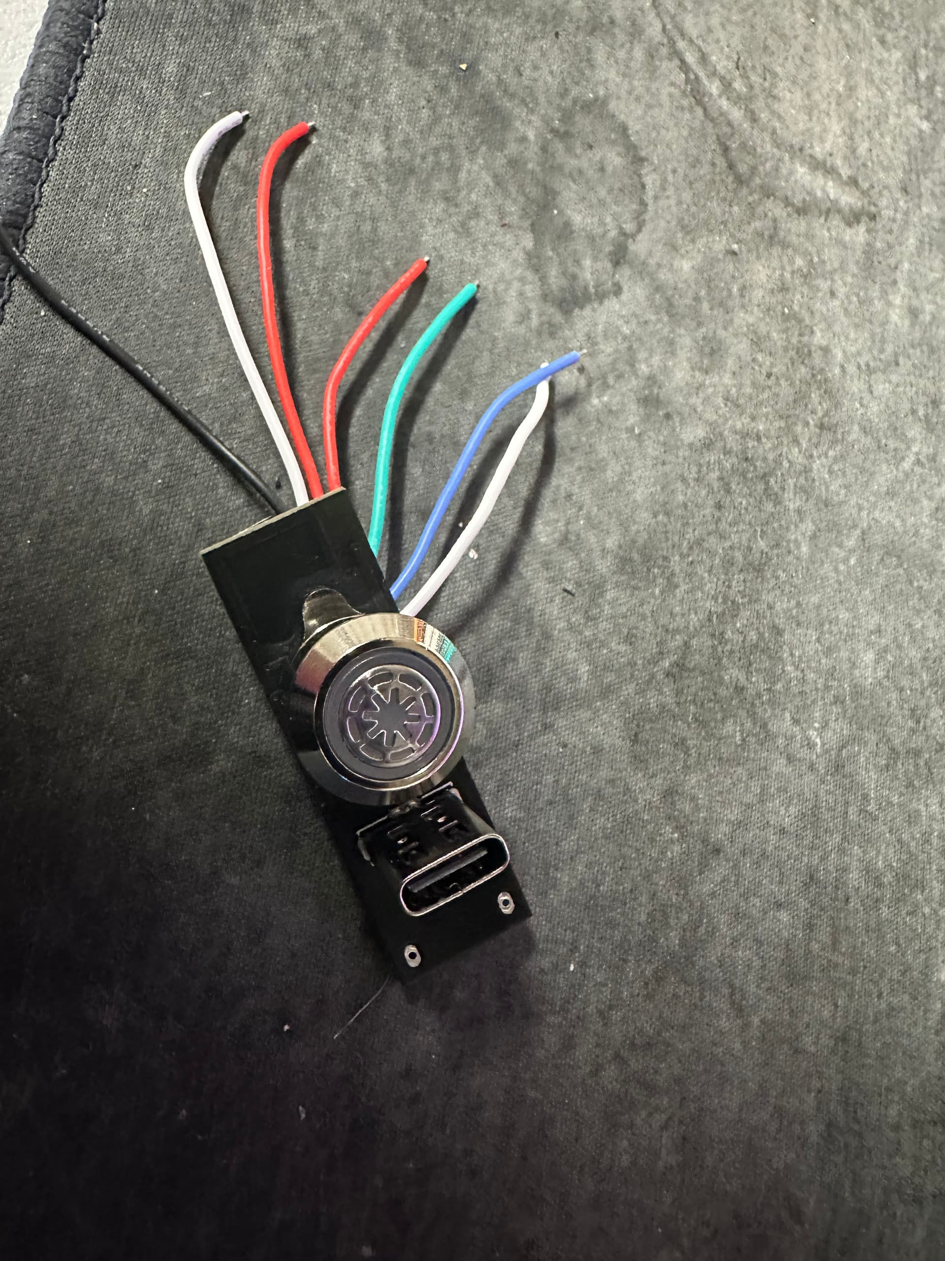
i have attached an image of the switch for reference. any ideas
There should be a manual, or a page or something that describes how to connect it.
Hi thanks for the reply,
got it a while ago for a Xeno board i was going to build, but i didn’t use it.
i got it off Ali exp it didn’t come with any documentation. the seller is no help.
Well, maybe buy from someone who has documentation next time…
Without documentation, you’re going to have to figure out what the wires do.
Usually it’s fairly easy to tell from the traces on the circuit board, but you may need to do some measurements with a multimeter if that doesn’t work.
i m not an idiot, and i didn’t post my question to be ridiculed.
i was just hoping some one had the easy answer, so i don’t have to go through that process.
first post and it will be my last.
thanks.
I apologize if my answer was a bit… irritated.
The irritation is not aimed at you, but at people who sell stuff without directions.
I did try to answer your question, and while the answer might be obvious to you, I don’t know you, so I really have no idea what skills level to write the answer at.
You’re welcome back anytime, should you change your mind.
appreciate the apology.
guess i am a bit quick to bite these days, seen and heard to much toxic behavior with on line communities. i owe you an apology as well.
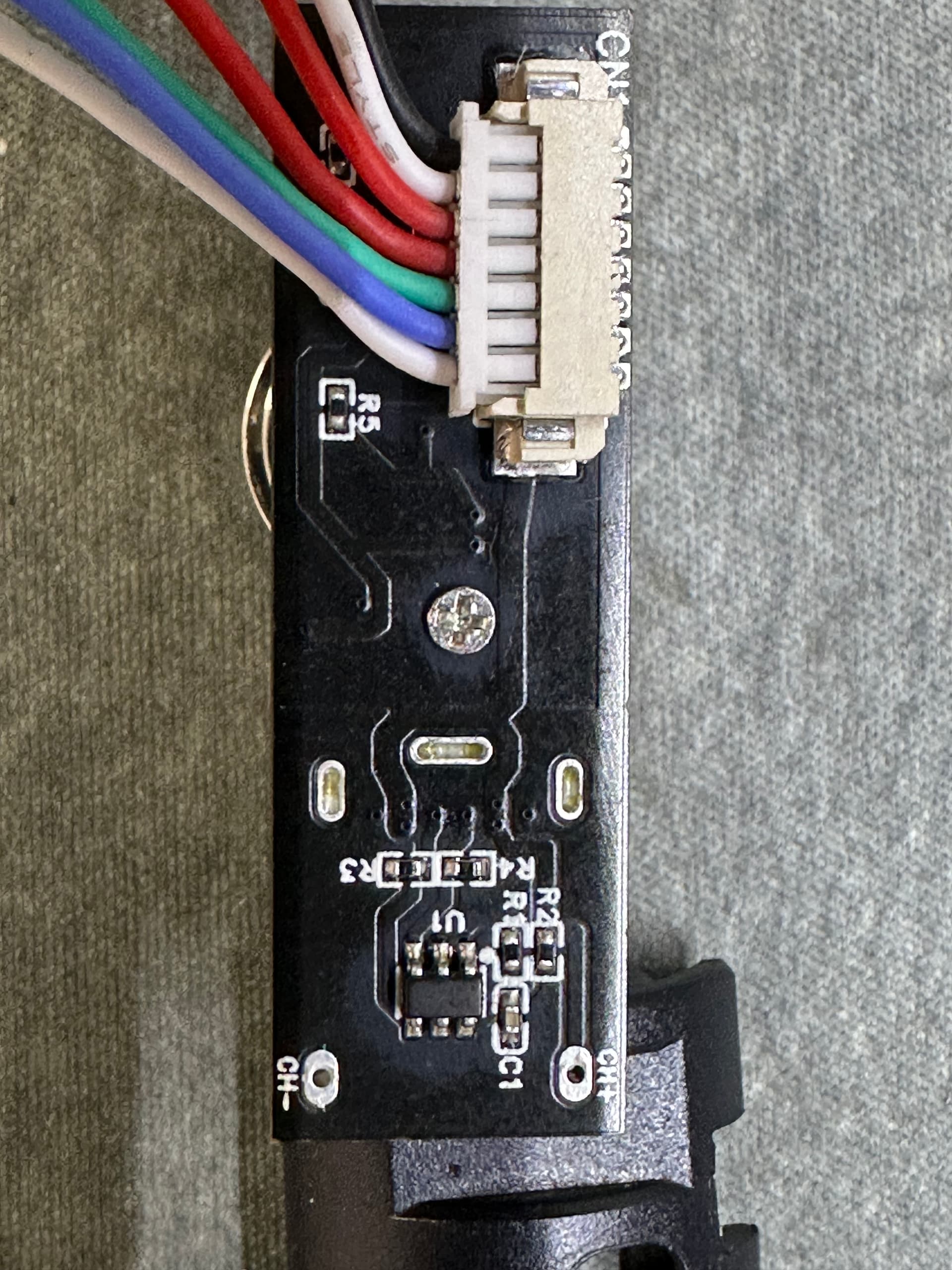
A pic of the back of the switch could help. Basically we’d need to see the origin spot of each wire. There’s a lot there… prob power for the led inside it (maybe a full neopixel - that’s 3 wires) then the usb could be just power or power and data. And finally the function of the switch itself, which is a simple inside one way and out the other.
A link to the product may also help ![]()
Also the “name”/reference number of the switch might help. I Know my son has a similar looking switch in his “no brand name”/Ali Express bought saber. If it is the same switch, it is only a white pixel (no data) so two wires plus two wires for the switch “action” itself, and the USB-C is only charging so two? more wires, but of course the pos and/or neg of the led & USB-C could be combined but since you have 6 wires, I doubt it. Then again, two red wires and “only” one black so common ground. Yes we need a pic of the back.
P.S. This place is the opposite of toxic. Profezzorn is the creator of Proffie board and Proffie OS. He has a lot on his plate. Yes sometimes his answers are a bit “rough” (no offense prof) but never with a bad intension. And also, I believe, English is not his first language, just like me (I am French speaking), and I know from experience that sometimes the intent of a message translated to English does not always go across as intended. If you are patient with “us”, you will only find people with good intentions here (trying their best to help).
I have a wiring diagram that should work, but it’s at home atm, and I’m at work until 5:00 (CST) or so.
Hi thanks for the replies,
I will post a pic of the back and the other info this afternoon when I get home from work. It is 09:45 AM here (AEDT) at the moment.
@ Olivierflying747-8.
I didn’t think it was a toxic group from all the feedback I had received from others.i appears The Crucible has an amazing reputation in the greater saber community that’s why i joined. I was to quick to judge and didn’t take translation in to consideration.
I thank you all for your help it is appreciated.
1 Like
That would be amazing if you wouldn’t mind.
ok i found the listing on Ali Express for the switch.
photos.
thanks.

Hmm, that’s not going to be easy, since there is something that looks like an active component on there. It might be a charging IC, although it could also be an EMI filter…
ok now you have got me, the charging IC i understand. the EMI Filter i don’t understand what it is
Might be because I wrote it wrong, I meant ESD protection, not EMI filter… EST protection is usually are a set of diodes that filter out static electricity.
I don’t actually think that’s what it is though
The ESD protection on the proffieboard looks kind of similar, but smaller:
https://fredrik.hubbe.net/lightsaber/v6/partmap.html#u40
ah, cool thank you, my thoughts are where it is located on the board it made sense to me that it is a Integrated circuit. although that doesn’t mean i am right.
awesome parts map thank you
My bad. Not the same component.