Before hand, im aware, that its probably totally unnecessary, but try to go with me, on this one.
I want to ligt up a RGBA module, it max out @ 1000mA but runs normally @ 700mA, all is great so far.
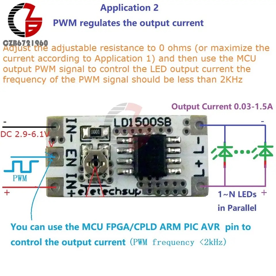
Instead of using resistors to control fI, ill use PWM controlled DC-DC Current regulators, to ensure perfect 750mA fI, at all times, no matter the voltage of the battery witch is between 3,2-4,2V depending on battery etc.
How would I program the PWM outputs to run less than 2KHz? And I guess a can use whatever output? because I only use them PWM controllers?
Is 813Hz good enough? That’s the PWM ProffieOS normally uses to drive LEDs.
Also, do you need to also control WS2811 pixels? If you do not, it simplifies things quite a bit because we’ll be able to use the timer that is normally dedicated to generating WS2811 signals for PWM instead. And when you say RGBA, do you mean RGBW? (Meaning that you need four outputs, not three?)
I’m upgrading my old ultra sabers, and they are RGB(A) “Amber”
No other fancy leds etc. just tired of having different boards in my sabers
One to rule them all.
UltraSabers used LZ4-20MA00 LED module LZ4-00R108_EN.pdf (1.1 MB)
, so I’ll just stick with that, and convert all hilts for two button control.
Ok, so you have four of these regulator thingies, right?
And you have Red, Green, Blue and Amber? That’s a little different…
There are essentially two ways to hook up these regulators to a proffieboard:
You hook them up to a PWM-capable pad that goes directly to the CPU, no extra components required. However, there are not that many PWM-capable pads, because most of those are hooked up to the FETs.
You hook it up to one of the LED* pads. However, those pads are open collector, which means you would need to add a pullup resistor. (A 10k resistor between IN+ and EN should work.) Unfortunately, doing it this way also means that the signal will be inverted, which means that LEDs will be on when the saber is booting and so forth. That’s possible to avoid, but it requires another inverter.
Now (1) seems better, but we still have the problem of finding four PWM-capable pads… A V3 board has Free1, Free2 and Free3 which can do PWM, so that helps, now we just have to find one more… Our options are:
Use one of bladePin, blade2Pin or blade3Pin. These can generate PWM signals, but doing so would use the timer which is normally dedicated to generating WS2811 signals. So using these pins means we cannot use any neopixels.
We could use the status LED pin. It doesn’t have a pad, but we could solder a wire to the LED itself. We would also need to disable the status led code, which can be done with the NO_STATUS_LED define.
We could remove a FET and then solder a wire to the pad that provides the control for the FET. This avoids all the inverting problems and gives us a pad that basically works the same as Free 1/2/3.
For a V2 board, we have no Free1/2/3 pins, so we start with 0 PWM capable pins instead of three. Also, we have no status LED, so we can’t use that trick either. However, if we allow the use of the WS2811 timer (so no neopixels) then the V2 board is able to use Data2, Data4, RX and TX for PWM, which is exactly the four that we needed…
Then there is the issue of driving four channels. ProffieOS uses RGB for all color manipulations in styles. This makes styles portable across sabers, but it does add some complication when driving 4-channel LEDs.
Here are a few options for how to do it:
Ignore it. Just use it like an RGB led.
Set up the fourth channel to activate for the right color, but otherwise do nothing different. This will make amber colors much brighter than other colors, which can look weird, but it’s easy to do, and the effect might be interesting.
Set up the fourth channel to activate for amber colors, and subtract that color from the other LEDs so that there is no duplication. This is a bit more complicated, but I think all the required support is in ProffieOS already.
Set up the fourth channel as a separate blade, then use a separate style to control it. This leads to some weirdness, but gives you direct control over all four channels.
So I’ll just use my stock of old v2.x boards, to drive my old sabers, that’s perfect.
The old sabers wouldn’t ever see a pixel LED, as it’s only an upgrade, if I ever decide to upgrade further I’ll go full pixel, like all my new blades, with soon to be 3.9 boards, and that would solve it
So:
I’ll use v2.x boards
No pixel LED’s
If I remember correct the Amber LED is only used for light on clash, in the old Diamond controller, so it doesn’t need to be part of the colour mixer, but go full on when there’s a clash could be awesome.
If you just want to use the fourth channel for clashes, then I recommend just setting it up as a separate blade, and then just use a simple style which just does clashes for that blade. However, since this is all configuration (no change in the wiring) you might want to experiment a bit with it to see what works best for you.
Can I have a base configuration example to work from?
I’ve been going thru the manual, and can’t seem to find the names of the outputs, they all refer to the FET outputs obviously.
It turns out that there is not 4 pins available on the V2 board after all, because two of the pins (tx & data2) share a timer channel. That means both pins can generate a PWM signal, but it will be the same PWM signal.
That gives me an idea though. I think it should also be possible to duplicate the signal from one or more of the LED* pads into the regular pads.
There are two candidates for doing this:
TX can duplicate LED1
Button1 can duplicate LED2
To do the first one, we would need to add the following line somewhere:
Unfortunately I don’t think there is a good place for it in the config file.
I would probably just put it here:
Now we can generate a configuration file for this. Basically we’ll just go to the configuration genrator (Proffieboard V2) generate a config file, either with a single 4-channel blade, or one with a 3-channel blade + a single-channel crystal chamber. Then we’ll do some search-and-replace as follows:
bladePowerPin2 → rxPin
bladePowerPin3 → blade4Pin
bladePowerPin4/6 → blade2Pin
Note that we’re leaving bladePowerPin1 as is, but the signal will still come out from the TX pin because of the gpio hack above.
It’s a little longer, but it’s probably better to keep it in the config file.
I would probably put this code at the end of the CONFIG_PRESETS section so that it is close to the blades[] array.
Looking at the AliExpress link, I realized something.
The controller you’re planning to use is in fact not a DC-DC regulator.
It’s just using PWM to prevent the output LED(s) from overheating. Only the average output current is regulated.
This is very similar to what ProffieOS itself does. The only difference is that the ProffieOS doesn’t measure the output current, it just calculates it based on a mathematical model of the LED instead. Not as reliable, but it does work.
You could save yourself a fair bit of trouble here by simply dumping the current regulators and drive the LEDs directly from the Proffieboard, but I think you knew that already…
Ya I noted the LED regulator part, in proffie, and wanted to use it, only thing was that it came with the note, that it might shorten the life of the led’s, and I wanted to prolong it instead but without limiting the output because of the variable voltage of a battery and a fixed resistor
I know it might only be theoretically, haven’t tried to see if there’s an observable difference just using a resistor, but can’t help thinking of the other solution that compensate fV.
It all started when I found the LED config though.
I might give it a shot.
It’s just that I use current drivers to my led project in the, building management world, where I come from so I was a little obsessed to current drive my old sabers, without static resistors.