So back to:
ORIENTATION_DATA1_PAD_TOWARDS_BLADE
ORIENTATION_SPKR_PAD_TOWARDS_BLADE
?
So back to:
ORIENTATION_DATA1_PAD_TOWARDS_BLADE
ORIENTATION_SPKR_PAD_TOWARDS_BLADE
?
We can keep those of course.
I still like the CW / CCW ones, but I also think it’s a good idea to create a POD page which shows exactly what each option means.
Done and done, as well as PR #579 for the update.
Well that didn’t fly apparently. PR closed, which is good because PB1.5 has data1 on the right.
However, BATT+ and SPKR pads are all on the same sides for 1.5, 2.2, 3.9, and M2.
Future boards might not work with it, but it does fit all current boards do while the current SDA and SERIAL from Teensy days does not.
so how about
    ORIENTATION_SDA_TOWARDS_BLADE = 0x02,
    ORIENTATION_BATT_POS_TOWARDS_BLADE = 0x02,
    ORIENTATION_SERIAL_TOWARDS_BLADE = 0x12,
    ORIENTATION_SPKR_PADS_TOWARDS_BLADE = 0x12,
?
I don’t want to add any new values based on pad locations.
It’s almost guaranteed that those will be wrong at some point.
Using the USB connector as the guide seems best, but of course, some day I might make a wireless board, and then that would be wrong too…
ORIENTATION_USB_CW_FROM_BLADE
ORIENTATION_USB_CCW_FROM_BLADE
and just assume people do that with USB facing them then?
I think that’s fairly reasonable, especially if we also go ahead with a POD page that actually shows it.
https://www.mouser.com/ProductDetail/STMicroelectronics/LSM6DSMTR?qs=dTJS0cRn7ogKkf7uVmbVmg%3D%3D
Is this a suitable substitute for the LSM6DS3H? Wasnt sure if the “TR” at the end of the part number made any difference.
The “TR” just stands for “tray” I think, meaning that the part comes in a tray rather than a spool.
Thank you sir. Have many people been able to DIY these on a small scale? I haven’t checked on the cost of a small amount of the PCBs yet. I know you said it may be cost prohibitive earlier in this thread. Not sure If Ill make the test rig or not as I don’t intend to sell any. Just want to have a new project. Handheld games are boring now.
AFAIK, nobody has even attempted to DIY a V3 board yet.
I HIGHLY recommend making a test rig, otherwise, how will you know if it’s working?
Unless you can just magically make perfect boards every time, the test rig will be immediately worth it.
Just looked at the BOMs for both the test rig and the pogo pin adapter. We would need to make both correct? I have most of the parts already on hand from making GBA SP PCBs. Should be no problem to whip these up quick.
Yes, you need both.
Any chance of a V3 with one of those 5 pin USB_C connectors? I messed around with the design of the 2.2, and at least from what I could tell, it would be tight, but it SHOULD be possible to fit one, at least the one I happend to be trying to use, just based on where the copper and connectors were.
Speaking of test rigs, where is the documentation for making them, I wanna make one (or two if 2.2 and 3.9 need different) just so I can test my PCBs before I start installing them cause when I screw up I am never sure if I did something or it was just broken, cause ive installed pcbs, nothing works, eventually I remove and just solder in a new one, flash the same and fixed. Would be nice to skip steps (and I won’t lie, once I get a hot air reflow station and a hot plate (I can’t afford no pcb oven… I don’t think) I wanna make me some purple proffies. Especially for a few sabers like Kevan and windu :P.
I assume most expensive part would just be getting stencils?
I also won’t like, part of me wants to figure out how to make a swappable soundboard that doesn’t itself need soldering at all, just pogos :P, but that is for later. Plus what I really wanna do is make them in CFX size so I could conceivably solder in a master board, then just drop a CFX or a proffie in. But I gotta lot of PCB design learning to do before I can make it work lol.
Unrelated, I know the 3.9 isn’t faster, but does the extra ram really not improve responsiveness? Like with fast multiple classes or blasters? I’m hoping it will at least massively reduce audio underflows. I was also curious, how big a difference is the more performant compilations supposed to actually make?
I just wish somewhere there was a list of the different options and like an image showing what they mean. Or perhaps labeling on the PCB on certain sides, like 1 and 2 printed on top and bottom and a/b/c/d on the 4 sides, and then you ask, which side is up, which side points at blade. Even if 1 is facing the blade and c is up instead of a facing blade and 2 up or w/e.
Cause I’m just guessing for a lot, like I know what the mosfets are, but they seem to be on both sides unless I’m missing something (and yes I am aware the top/bottom of the pcb is way less important than which side is facing the blade).
That was one thing that was less clear compared to setting up CFX cause its manual is thicc.
I was always curious, does it actually care which direction the blade is pointing vs its opposite? Cause it seems like you can also “stab” with the pommel, but I wasn’t sure if that was normal or a sign I screwed up.
V3 will not have a USB C connector.
Maybe when I get to V4 ![]()
There isn’t a lot of documentation, but what there is can be found here:
https://fredrik.hubbe.net/lightsaber/v6/test_rig.html
(Make sure to follow the links for the breakout board and pogo pin adapters for more info.)
Hobby-level stencils are not expensive, just go to oshstencils.com and order some.
For a V3 board, getting the boards is probably a lot more expensive than the stencils, because oshpark boards will not work for V3 proffies.
It can be tricky to get enough current through the pogo pins…
It’s a lot of work, but if you are having fun doing it, then go ahead. ![]()
The RAM has no impact, because the code doesn’t actually use the extra RAM for anything.
The extra FLASH can be helpful, because you can increase the optimization level when compiling the code.
The extra RAM does not help with audio underflows.
However, the V3 has an SDIO interfaces which can read data from the SD card faster, which does help with audio underflows.
I assume you mean turning on optimization?
It really depends a lot on what your styles look like, and how many LEDs you have.
If you have simple styles, it makes no detectable difference. If you have big complicated styles and lots of LEDs, it can make things much (maybe up to 2x) faster.
There are definitely some gestures and effects that care (like drag / clash / stab)
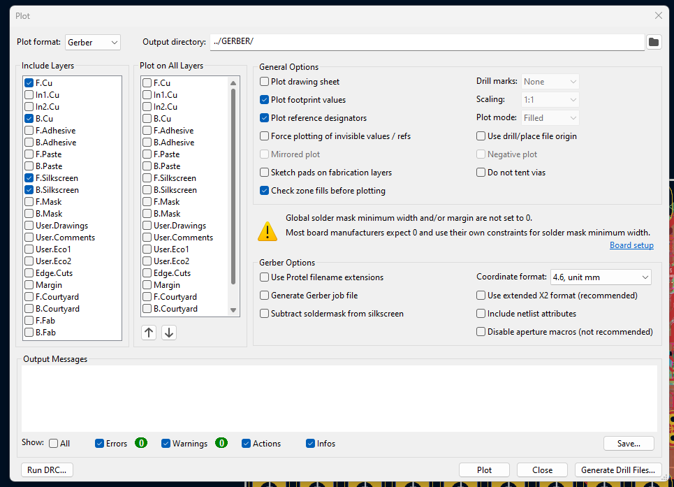
Is there a padawan section for learning how to get the Gerber files from the KiCAD ZIP? Ive never used KiCAD before. Stupid question I know. Sorry.
The default options are good for the most part.
You’ll need the F.Paste and B.Paste layers if you’re making stencils though.
I’m not an expert on Kicad really though, so for real advice on how to use kicad, read their documentation and go their support forum (or whatever they use).
Ok cool. I just wanted to make sure that I was clicking on all the features that you used/needed to be put into the PCB in order for it to work properly. Thank you for all your help here!