Proffie wiring crystal chambers and npxl connector

Hi All,

I have an npxl connector by Dmitry and want to add a crystal chamber to this build, I have some RGB 5mm anode leds that I want to use but that will use up atleast 2 fetts.

my question is how, if at all do I wire it up?

I was planning on using this:

V2 – blade + pcb leds in parallel
This way a single Data wire controls both blade and
on-board connector leds in parallel (mirrors).
Data wire is soldered to D2 pad with on-board 330 ohm
0603 resistors R1 and R2.
image

as the setup

i have enough pads but I’m curious about whether or not there’s enough power to power it all. also I would need to add a 3 blade to my config, right?

Max,

If you wire it the way you say, V2 Shtok Nxpl Lit Connector, you will have 2 blades. First blade is the Shtok connector and Main Blade. Second blade is the crystal chamber RGB Common Anode. You wire it exactly as in your diagram you posted; however, instead of the positive, negative, and data lines connecting directly to the neopixel strips (as in your diagram) you connect those to the NXPL Lit Connector. The Shtok NXPL connector merely translates the positive, negative, and data to the neopixel blade.

Now, the Shtok connector diagram you posted has 2 data lines, and appears to be V4 config, when you said you were using V2 Config which makes accents and blade parallel. V2 only has one data line feeding the neopixel blade and accents, so use the right diagram for the V2, and wire it per the manual.

I will say that using a neopixel for your chamber might make your install easier, but the common anode RGB LED will work. When it comes to accents, the 5 neopixels and the RGB LED don’t draw near as many amps as the main blade. The common anode RGB LED will be driven off fets 4,5,6 just like your diagram, and that won’t even tap 1/10 of the capabilities of that mosfet. The main blade and Shtok connector will use fets 2,3 (per your diagram), and those fets can handle the blade and the 5 pixels on the Shtok Lit NXPL Connector.

Bottom line, outside of using the V2 Shtok NXPL Connector diagram, wire it just like you have in the photos above.

Tom

The npxl document only has v4 diagram to how to wire it to the board.

i take it then that this is wrong?

BladeConfig blades[] = {
{ 0, WS281XBladePtr<132, bladePin, Color8::GRB, PowerPINS<bladePowerPin2, bladePowerPin3> >(), SimpleBladePtr<CH1LED, CH2LED, CH3LED, NoLED, bladePowerPin4, bladePowerPin5, bladePowerPin6, -1>()
{ 0, WS2811BladePtr<5, WS2811_ACTUALLY_800kHz | WS2811_GRB, blade2Pin, PowerPINS<bladePowerPin1, bladePowerPin2, bladePowerPin3> >(),
, CONFIGARRAY(presets) },

should it be?

{ 0, WS281XBladePtr<137, bladePin, Color8::GRB, PowerPINS<bladePowerPin2, bladePowerPin3> >(), SimpleBladePtr<CH1LED, CH2LED, CH3LED, NoLED, bladePowerPin4, bladePowerPin5, bladePowerPin6, -1>(),

I think this is what you want:

BladeConfig blades[] = {
{ 0, WS281XBladePtr<132, bladePin, Color8::GRB, PowerPINS<bladePowerPin2, bladePowerPin3> >(), 
     WS2811BladePtr<5, WS2811_ACTUALLY_800kHz | WS2811_GRB, blade2Pin, PowerPINS<bladePowerPin2, bladePowerPin3> >(),
     SimpleBladePtr<CH1LED, CH2LED, CH3LED, NoLED, bladePowerPin4, bladePowerPin5, bladePowerPin6, -1>(),
  CONFIGARRAY(presets) },

If so, make sure that NUM_BLADES is set to 3.
Also make sure you have SHARED_POWER_PINS in your config file.

Blockquote

just so I’m understanding this correctly:
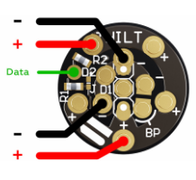
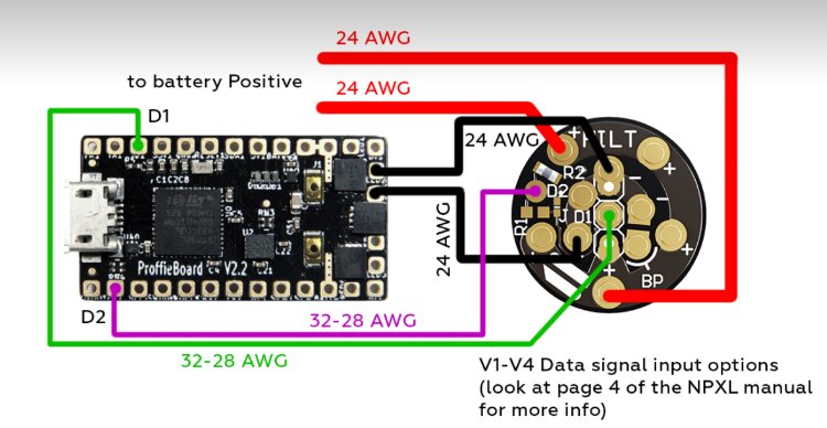
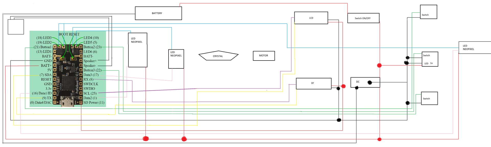
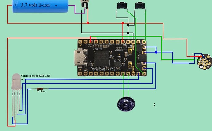
Wiring Diagram

wiring diagram morningstar

and yes the positive and negs will be 22 AWG. This is the v2 i’m doing as mentioned before. sorry about the confusion but the npxl manual only has v4 wiring diagram and I want to make sure I’m clear on the next steps.

p.s @MegtoothSith i added 30 ohm resistors to the blue and green on the anode led.

with that in mind the config is as follows

BladeConfig blades = {

blade:
{ 0, WS281XBladePtr<132, bladePin, Color8::GRB, PowerPINS<bladePowerPin2, bladePowerPin3> >(),
NPXL:
WS2811BladePtr<5, WS2811_ACTUALLY_800kHz | WS2811_GRB, blade2Pin, PowerPINS<bladePowerPin2, bladePowerPin3> >(),

CRYSTAL CHAMBER RGB ANODE LED:
SimpleBladePtr<CH1LED, CH2LED, CH3LED, NoLED, bladePowerPin4, bladePowerPin5, bladePowerPin6, -1>(),
CONFIGARRAY(presets) },

clarifying now before I wire anything. just want to be sure I got it right.

The blades array config Fredrik just gave you is as if you are running the 5 Shtok LEDs on the connector as independent blade, which you are not. YOu only have one data line in your diagram for the main blade and the Shtok connector. That is V2. SO you only need your main blade array, you can ditch the second blade labeled NXPL in your above quote. You need only the main blade and your crystal chamber RGB Anode blade. THe 5 LEDs on the Shtok connector will mirror what your blade does.

TOm

1 Like

so the answer is:

BladeConfig blades[] = {
{ 0, WS281XBladePtr<132, bladePin, Color8::GRB, PowerPINS<bladePowerPin2, bladePowerPin3> >(), SimpleBladePtr<CH1LED, CH2LED, CH3LED, NoLED, bladePowerPin4, bladePowerPin5, bladePowerPin6, -1>(),
SimpleBladePtr<CH1LED, CH2LED, CH3LED, NoLED, bladePowerPin4, bladePowerPin5, bladePowerPin6, -1>(),
CONFIGARRAY(presets) },

right?

thanks Fredrik and Tom.

oops, duplicated.

i meant,
BladeConfig blades[] = {
{0, WS281XBladePtr<132, bladePin, Color8::GRB, PowerPINS<bladePowerPin2, bladePowerPin3> >(), SimpleBladePtr<CH1LED, CH2LED, CH3LED, NoLED, bladePowerPin4, bladePowerPin5, bladePowerPin6, -1>(),
CONFIGARRAY(presets)},

This would be the right answer if the LEDs on the pogo pin connector are hooked up in parallel. The data would then be shared and duplicated between the blade and the 5 pixels on the pogo pin board.

If they are hooked up in series, then you should be using subblade to address the first five pixels as a separate blade.

thank you fredrik, that is what I meant by v2 that they are setup in parrallel. awesome now to actually do it.

Hi, i have question.

Hi,

I’m trying to put my sword together and due to the type of construction and the arrangement of components, I try to get rid of the number of wires for this, based on the generator, I created my diagram. Is it possible that the connection could be like this? I do not have the engine connected in the diagram, so I will be grateful if you show how to connect to register it as an LED to control its rotation.

Please start a new thread instead.
Also, this diagram has a lot of stuff in it, is there anything in particular you want people to inspect?

thx i open new topic: Assembling to the proffieboard2.2