My previously working lightsaber stopped working after I added a BT-909 module. None of the buttons seemed to do anything and my computer wouldn’t detect the Proffieboard when connecting with USB. I though I had fried the Proffie so I completely disconnected it and now my computer is able to detect it again. I reconnected the BT-909 and did an A/B test with the only difference being the power wire being connected/disconnected and this was indeed what was causing the issue. Does this seem normal?
I also did the same A/B test with the ProffieOS workbench. The workbench was able to detect the board with either USB or Bluetooth but it would loose signal after a few seconds.
I wasn’t aware about the capacitor. I followed the wiring diagram I generated from here: Proffieboard V3 . What kind of capacitor is recommended and where should it connect?
The Proffie v2 PDF manual says to connect the Bluetooth power to the 3.3v pin but the Proffie v3 manual says to use the SD Power pin instead. Is there a difference?
The SD Power pin can be switched off separately (typically to power down the SD) by ProffieOS, that’s pretty much the only difference. If you’re using SD power, connect the cap between it and ground instead
Not really if you’re using a MOSFET for the negative. Fredrik might have more info about it, but at that point it’s just a matter of whether it switches on/off with the SD card or with a set bladestyle and IDLE_TIMEOUT.
It seems to me like putting it on a MOSFET would be more desirable because you get more control over specifically the BLE module and it’s not dependent on the SD card. Especially since it’s generally not recommend to connect things to the SD because it’s (maybe just planned?) not necessarily consistently on all the times the saber and everything else is.
However, it’s slightly less pretty in the config to wire it to a MOSFET, though I could think of some creative and useful ways to do things there…
I’m a complete newbie to this - The Bluetooth module’s ground is connected to a ground pin in the Proffie so I don’t think I’m using a MOSFET for the negative?
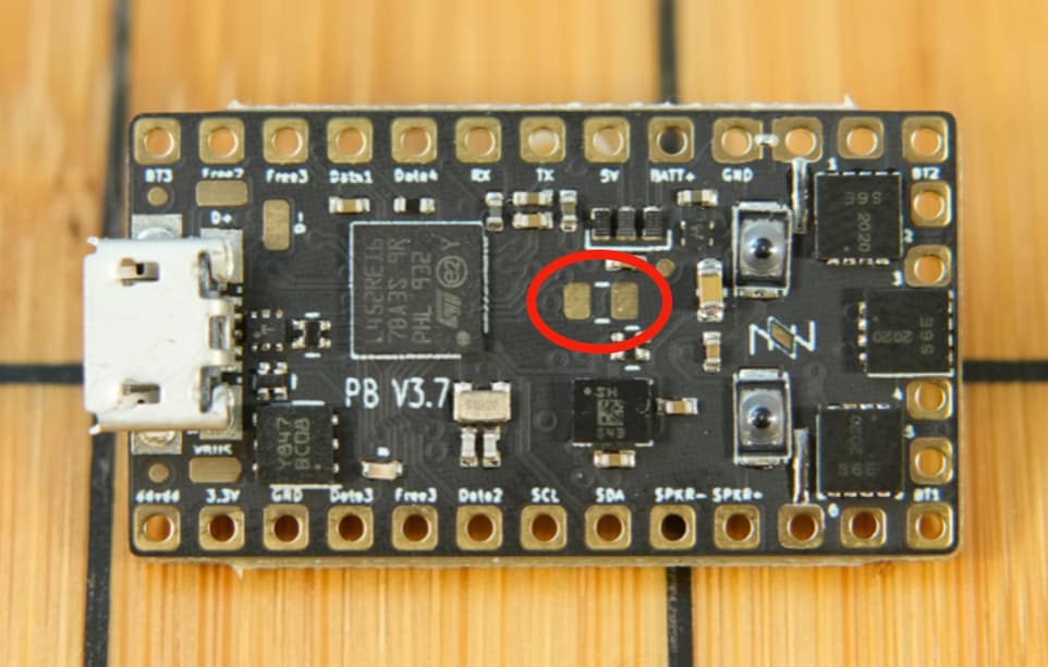
And that’s good to know - where are these pads located on the board?
On the bottom (side with the SD card slot) of the board, there’s two big gold rectangular pads side by side, the cap would go there)
Correct, the v3 wiring diagram generator shows connecting to normal ground and relying on SD Power to turn the BLE on/off instead. This is an either or situation; you’d either use a MOSFET and 3.3v or normal GND and SD Power (SD Power is just 3.3v that can be turned on and off, serving the same function as the MOSFET)
@profezzorn I’d be curious to know pros/cons of these setups and the reasoning behind preferring SD Power, specifically because of previous claims it shouldn’t be used.
SD Power certainly seems more convenient for wiring and programming.
Got it! Thanks for the fast replies, it’s much appreciated.
I’ll get my hands on a capacitor and try this. I’ll report back here to let you know how it went.
There is currently no code that turns off SD power.
I will add some at some point, and when I do, it should also take bluetooth into account, however, there is always a chance I mess it up somehow, so it might be safer to not use SD power for bluetooth.
If you do have an available LED* pad, using it to gain control over bluetooth power is not a bad idea.
SD power should not be used for anything other than bluetooth though, because when do add that code to turn it off at some point in the future, whatever you hooked up there is likely to stop working.
Just to confirm, as I’m about to do a 3.9 install with Bluetooth (if I can fit the module in - it’s gonna be tight) but are the two circled pads the ones that I need to use for the Bluetooth capacitor?