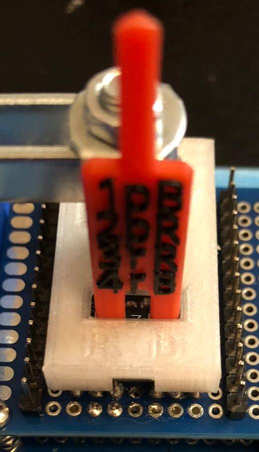
So I can see between the legs if I am on the buttons or not. The window is just wide enough to allow rocking but you can’t see much from the side.
So I can see between the legs if I am on the buttons or not. The window is just wide enough to allow rocking but you can’t see much from the side.
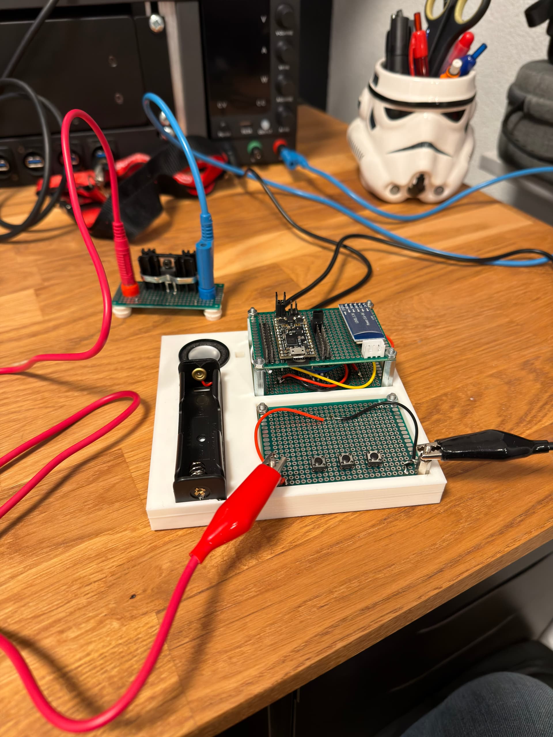
As you can see on the picture above, I decided to add header pins on the left and right of the ProffieBoard for modularity, in case I want to test other components than what I plan to add to the test bed.
I will solder BATT+/BATT-, the LED strip (POS, NEG & DATA) and the JST connector for the “on board” OLED to the bottom PCB board.
I was wondering what can I get away with not soldering and just using the headers and Dupont connectors?
I am guessing:
These, I beleive should be ok:
These, I have no idea:
I will not be testing home made blades with this test bed.
Anything else I could consider before I start soldering wires to the bottom of the spear tip test probes which would make adding more to the “sandwich” impossible with my lack of de-soldering skills?
As always, thanks for any tip.
Cheers
My recommendation is to add two rows of header pins.
The first and the second row would not be connected, but can easily be connected with a jumper.
Then you can have buttons, neopixels, leds, speakers, whatever connected to the outside row, but for experimentation you can remove the jumpers and connect something else with dupont wires.
I am not exactly sure how would a second row, not connected to anything, help even with a jumper ? The only jumpers I know of, are usually as tall or taller than the pins. Do very low height (1 or 2 mm tall) jumpers exists ? My pins are about 5 mm tall (past the plastic).
I made a “drawing” for better understanding:
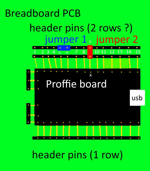
Jumper 1 connects “nothing to nothing”, so you must be talking about a jumper 2 but it connects pin “x” to “nothing”.
After further thought, if I was to add a second row, wouldn’t it be more convenient to connect both “pin1” together, “pin2” together, … & “pin15” together and not have to bother with tiny jumpers ? Plus I have fat fingers and it is already not so fun to play with the individual Dupont connectors! ![]()
Anyways, I am running out of room on this breadboard, but I will consider it for the next version of my test bed. I know, I know, it is not finished yet and I am already considering a newer/better version and I haven’t even finished my first saber. ![]()
Oh, I didn’t mean that the second row would connect to nothing.
The second row connects to leds, speakers, buttons, etc.
The jumpers (like jumper 2) lets you disconnect those things so that you can experiment with other things.
The idea is that the jumpers stay in place most of the time, and they avoid having any wire clutter most of the time. But later you can disconnect any of of the jumpers and plug in a cable instead. This is how my breakout boards work.
Oh, I see so the only thing that connects to the spear tip probes is the first row of headers and the second row connects to the on board devices. If a different device needs to be tested, remove the jumper and use a Dupont connector on the first row to connect it instead.
Are you by chance willing to share the STL of this test bed?
In the end I created my own design.
But I’m happy with the result so far!
Test board has
I have a LED strip that connects to the top white connector. I did not include it in the case. I wanted the ability to change it with a different LED.
Now I can finally continue with the Blade Styles On SD Card feature i was working on without having to open up my saber the entire time.