I should be getting my spear tip test probes and clamps this week. I am already thinking of rebuilding my test bed to version 2 with 3 non latching buttons and an OLED (unfortunately OLED was not in my cart when I placed the order so it will have to wait )
But I am thinking to add latching buttons to simulate blade detect pin, clip detected pin and a detonator “slider” button.
Do I need 3 latching buttons ? I was hoping that blade detect pin and clip detect pin could be one latching button, and have non latching AUX2 in parallel with the latching button for the detonator slider.
Would this work? And what would I need in my config for AUX2 in parallel with a latching switch for my all-in-one multi_prop config “environment” ?
As always thanks in advance for any advice.
PS: I now have my multi_prop.h working almost as initially planned (I am still trying to add a unique button/event combo with an EXTRA_LONG button push but for now it is working great as it is currently in my PR to Github master.
Latching buttons can be helpful, but I don’t have any on my test platform. Most of the time I just hold a tactile button when I want it to work like a latching button. I also have easy-access header pins that I can use to hook things up (like a latching button) if I need it.
It would work, your config would either have a latching button on a switch, not both.
Fair enough, so if I have in my config 3 non latching buttons and one latching switch in parallel with one of them. Instead of having to hold that button, I can just flip the switch and it will “work” like a latching switch?
But the events generated would be different, right?
There would be a time out (“something is eating our clicks”). I am mainly thinking about the detonator latching button in this case.
You can have a latching button, and a momentary button on the same physical pad, however, you can’t really use both of them at the same time, because there is no way to tell them apart.
In your config you can have a LatchingButton or a Button for that pad, but you should not have both at the same time. It’s true that they generate different events, but some props listen to both events, which which would be weird. (You would get the effect of a latching button AND a momentary button at the same time, regardless of which button you actually use.)
Should be fine. I2C is low current and not high enough frequency to require waveguides or anything complicated. As long as the wires aren’t overly long (several feet) it should work fine.
I checked the config generator, if my eyes are not deceiving me, no wires are in common between OLED and color displays not even pos and neg. So one “four pin” jst dedicated to OLED only is enough.
Once I get my hands on a color display, I can add a connector for that and the connections for it won’t “interfere” with the connections for OLED.
Cool. I just need to plan for enough space, so both screens can fit on the bed.
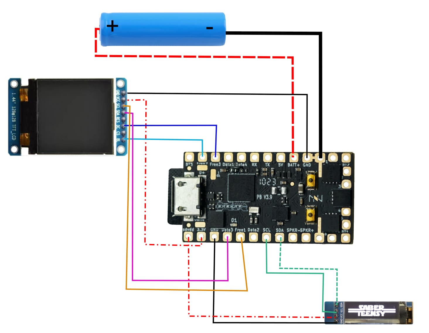
One is SPI an the other is I2C. I2C is 4 wires and SPI-based screens use 6 or 7 pins. And they are so separate that you can use SPI and I2C at the same time. I’ve made the following graph to connect both.
Technically, you can share GND, but no of the signal nor positive pins are shared.
SDPower has a FET that can turn off the display, but I don’t know the total amperage possible of that FET. Now that I’m looking into it, it might bring some issues with sharing OLED. But I guess you could share from 3.3V directly.
I went and checked and the FET is rated for 3A and the color display consumes 80mA while the OLED 128x64 25mA. So yes. I know see that I can wire all from the same pins. Would you recommend to use SD or straight 3.3V? I do plan on testing 1 SPI + 2 I2C.
The idea used to be that we use SD_VDD for displays so that they could be disabled when we don’t need them. However, after adding code to disable them over I2C, I’ve noticed that most of them draw very very little current when off, so the whole SD_VDD thing might not be needed or helpful.
So basically, it doesn’t matter which one you use.
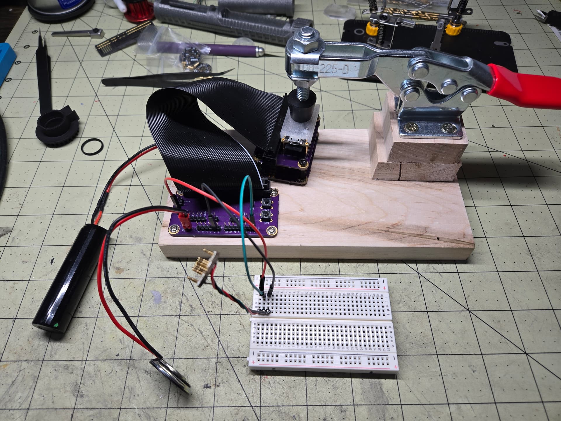
I got my spear-tipped pins and clamps (I got two).
Is there a spot I should aim for the clamp to make physical contact on the ProffieBoard and/or a spot I should avoid?
I know I need to avoid the buttons and the USB port, but if I aim for the center, is that good enough ? And since I have two clamps, one on the fetts & one just behind the USB port ?
Also I would like to add a latching switch to simulate blade detect pin. I am guessing the “negative” wire could be connected to the common ground of the other switches (I have 3) ? And I will be adding wires for a color screen (future upgrade), so the second wire shouldn’t go to Free3 or BT3, where else could it go ?
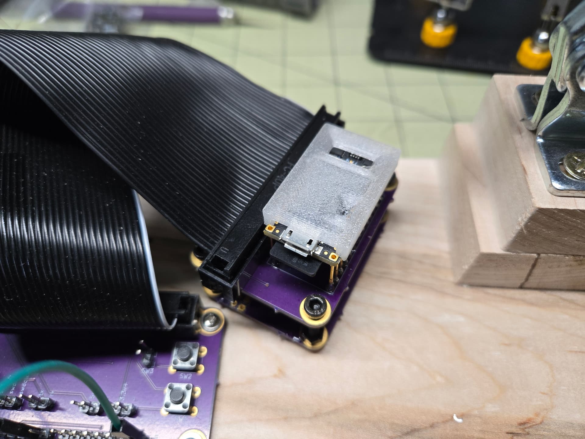
It is going in the printer in a few minutes. PETG is the only one I have in transparent and it is already loaded from last print, plus it’s a fitting color.
One question, it is able to slide along the length of the ProffieBoard, any particular reason you didn’t add a partial “front and back” wall, just enough to wrap around the corners to avoid sliding?