So long story short here, I believe I have found a way to dramatically decrease power consumption in the low power operation state of Proffie V2.2 boards and I wanted to share my progress so far in case others are interested in contributing or providing feedback. I’m curious to see if this approach works similarly on V3.9 (or older V1 boards for that matter) too.
First, some background. If you are like me you’ve got a few Proffie installs that use kill-keys to restrict battery drain, but there is at least one or two hilts sitting on your shelf yet to be installed that really are not ideally suited for a kill-key installation (either too hard to access said kill-key without a fair bit of disassembly or just straight up not big enough for a full port or switch). I understand that v3.9 has some intended improvements in this regard but they may not be implemented yet (I don’t have a v3.9 board yet, so I may be mistaken). Point is, current power management on Proffie seems to still leave a fair bit to be desired and I’ve come across many posts of people saying they typically only get a few weeks of standby time which largely lines up with what I have seen on several of my hilts.
So just how bad is the current setup was my first question. I hooked up a high-precision current probe and compared Proffie V2.2 with stock V7.12 against hilts with Goldenharvest GHV3 and Xenopixel v3 installs which I felt fairly accurately represented other typical alternatives on the market and should serve as a baseline for standby current consumption.
Results from my findings are outlined below. The chart outlines what each line represents, but obviously each entry is taken when the corresponding board is in sleep or low power mode.
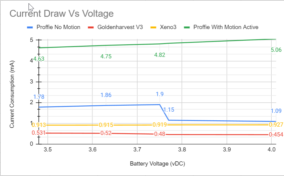
Three very interesting observations:
-
Proffie registers higher current consumption than both Xeno and GHV3. I suspected this would be the case given that my Proffie hilts always seem to run out faster than my Xeno / GHV3 hilts, but this was confirmed in the above.
-
Proffie has seemingly two different low power modes: One with the motion controller still active, the other with it disabled or timed out. For testing purposes, I took the “Proffie No Motion” readings with “ENABLE_MOTION” commented out–which is not truly a fair comparison as it bypasses a few fringe cases I’ll comment on below, but does give a theoretical “best case” with stock Proffie code. To get the “Proffie With Motion Active” readings, I uncommented “ENABLE_MOTION” and enabled at least one motion switch activation function (twist to activate for example). I found that this resulted in the motion controller chip never going to sleep, which makes sense if you are expecting to be able to twist the hilt at any time to wake it up (by definition, it can’t go to sleep). Current consumption in this second mode was substantially higher @ approximately 4.8mA vs the ~1.5mA average consumption for the “No Motion” state however I was frankly unable to get into this mode naturally (without turning off ENABLE_MOTION) which is concerning since I did try this with stock profile configurations. I am guessing there may be a bug somewhere preventing the motion chip from powering down but I haven’t looked into this yet.
-
Alarmingly (and not pictured in these results), I found that some fonts prevented the Proffie from ever entering low power mode, resulting in a constant 17mA draw indefinitely. I am not sure yet what the cause for that is and perhaps it has been identified and since resolved, but this obviously drops the battery shelf life to a matter of days. I am not including this in my findings since this is clearly an OS level bug and not the intended behavior of the device as-is, hopefully someone else here can comment on this case / investigate more closely (I can provide details on which fonts I was able to replicate this on reliably).
So what does this mean exactly in terms of shelf storage time. My philosophy on standby time ratings is that it should be time to reach 50% capacity versus how long does it take to discharge 100%. Arguably, if the battery cell is at or below say 30% state of charge it is not going to last particularly long and therefore it really doesn’t matter how long it takes to get to say 0% since the hilt can’t be used meaningfully at that point. I chose to classify my “expected runtime” calculations in terms of an arbitrary 1500 mAhr discharge capacity, which I estimate to be between 30% and 50% for most commonly sized 18650 cells.
For stock Proffie firmware as it stands today (as of V7.12), I estimate 1500 mAhr discharge occurring after approximately 41 days for optimized sound fonts (ones that do not require motion controller remaining active in low power sleep) or 13 days for motion enabled fonts / prop files which is realistically most if not all fonts I’ve tried so far, but perhaps I was doing something wrong. Compared to the likes of GHV3 which should be around 125 days for equivalent discharge, or Xeno3 at approximately 67 days, that is a fairly substantial difference.
Next step was to identify what the major draw was on Proffie. The obvious player was the processor, and that ended up accounting for about 95% of the power consumption as expected (will get into how I determined that later on). As it turns out, the processor isn’t entering sleep mode at all currently, it is simply switching to a lower operating frequency in low power mode to reduce current draw. This lines up with the measurements I took.
I then came across this thread during my research where an even lower frequency was used, but it produced instabilities:
Instabilities aside, I decided it was worth trying this configuration to see what the impact was. The claim was that it increased standby time up to 2 years which sounded promising. Results were a bit less impressive unfortunately, shown below (“LP Run” against “Stock” firmware):
Apparently since I am a new user I can only post one picture, so just imagine another beautiful chart here showing a shift from 1.2 mA to 0.600 mA at the lowest
While better, it was still producing about 700 micro-amp current draw on average (note the transition between 0.625 mA and 1.4mA @ approximately 3.65vDC, I have some theories as to why that is happening but nothing conclusive yet). This is largely on-par with at least the Xeno v3 board, but this can be better still.
STM32L4x processors are specifically designed for low power operation so I knew there had to be a way to improve this, especially since we aren’t currently leveraging any clock stopping functionality really at all at present. Per ST documentation, the STM32L4 series chips theoretically could be drawing as little as 30 nano-amps (0.03 micro-amps, or 0.00003 mA) with varying levels of sleep mode capabilities, but it’s complicated by the fact that not all power operation modes are recoverable so this limits options just a bit.
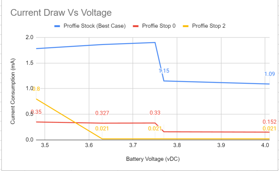
My first attempt was to try STOP 0 mode which, per ST, should result in 110 micro-amp (0.110 mA) sleep current operation and is the most mild / simple solution. It stops the clock, powers down most peripherals while retaining full memory storage leaving full “wake and run” recovery a possibility.
Results from this were very promising:
Still can only show one chart, just imagine being blown away by a chart showing 0.35mA to 0.15mA consumption in STOP mode
Based on the above estimates, this should result in 1500 mAhr draw over approximately 300 days, plus or minus a bit (just shy of my target of 1 year).
So why hasn’t this been implemented in Proffie already? The main challenge as I understand it was figuring out how to wake the processor back up once it was in this mode, since ST defines only 5 discrete wake-up tolerant GPIO pins (PA0, PC13, PE6, PA2, PC5)–2 of which don’t even exist on the processor used on Proffie V2 due to its form-factor. Obviously, if we have to go in and cut power to the board to wake it back up again that largely defeats the purpose of this exercise (not having to disassemble the hilt in between uses and having it “just work” automatically with minimal input or exterior penetrations).
Fortunately the chip has an onboard RTC which gives several unique advantages. First and foremost, it means we can schedule wake-up events at set intervals (actual time-based units) without having to trigger an actual pin-level wake-event. In other words, we can put the chip in sleep (STOP) mode for a number of seconds, wake back up and see if we should stay awake, then immediately go back to sleep again if not to the tune of only being “awake” for a few dozen instructions (negligible impact on overall consumption). We use this technique in battery management controllers for time-based data tracking and maintenance functions.
So the strategy was simple then, set up a STOP interval of 4 seconds inside a loop that evaluates whether either the auxiliary button or power button was depressed when it wakes up (so at most, the operator has to depress one of the buttons for 4 seconds). If not, it goes straight back to sleep. If so, we exit the loop and resume normal clock speeds and re-initialize peripherals and off to the races. The result was basically best of both worlds: low sleep current draw without having to make any hardware changes. The only real drawback to this was that the board can’t be woken using exclusively gesture control (so a bummer for any hilts that have no hardwired buttons). In theory, this approach could be easily adapted to re-initialize the motion controller in between sleep evaluations to check for specific motions, but I don’t currently have plans to investigate this further at this time and it would likely have a non-negligible impact on the sleep current savings. I have not yet decided whether it makes more sense to simply reset the CPU on wake-up to perform initialization, or to just re-initialize peripherals upon wake individually. Currently I have it performing a full CPU reset on wake as this is on par with GHV3 / Xeno3 functionality and for my purposes this is ample, but it is theoretically possible to just pick up where we left off before going to sleep with a few initializations (motion chip / I2C bus in particular).
Still, I wanted to see if there was a way to improve on this further since the chip should theoretically be able to get down to about the 30 nano-amp range which would be the ultimate holy grail as far as low power sleep.
Switching from STOP mode to SHUTDOWN mode (the lowest possible current draw) the results were extremely promising:
And again, be blown away by a theoretical chart showing 0.019 mA current consumption in all its glory
Obviously this is a further substantial improvement and we go way beyond a 2 year theoretical standby time (to the point where it doesn’t really make much sense to compute as other factors like internal self discharge or protection circuit consumption start to weigh in).
The problem though is that memory is completely obliterated during this sleep stage which means the approach used for STOP mode will not work (saber will forcibly restart every few seconds which is a non-starter). So this requires an actual wake-up pin to utilize properly.
Of the 5 pins designated as wake capable, 2 of them are not available on the Proffie V2 processor and 1 of them is the INT pin coming from the motion chip. This leaves PA0 (id-neopixel_data) and PA2 (TX). Now this is where I’m looking for feedback from the community, since neither pin is exactly ideal. The data pin has an inline resistor (and is presumably used on most existing Proffie installs already since it is the recommended data pin to use for pixel), but the TX pin is pulled straight-through. My intention is to use TX as the wake-pin, but I realize this will break backwards compatibility with existing hilts that have serial based Bluetooth chips (which apparently use RX and TX pins). For me, this is an acceptable trade-off (shutdown capability versus bluetooth capability) but others may not feel that way so obviously this should be split off as an optional improvement. Given how successful STOP mode was, it may not be truly needed for most use cases (though smaller cells would obviously benefit still).
Full disclosure, I haven’t yet sorted this out yet as I appear to be fighting internal pull-ups on the pin at the moment and so it wakes up immediately on shutdown with the TX wake enabled (I suspect it may have to do with the internal UART peripheral transitioning from active to inactive during the shutdown command and then triggering itself as a result, but I haven’t had time to sort out decoupling it prior to the shutdown command). This should be a fully solvable problem with the correct register manipulation though. I was able to take the current consumption measurements with the chip forcibly held in shutdown, but I have not yet been able to successfully wake it with the desired behavior. My experience with STM32 MCUs is admittedly somewhat limited compared to other brands so I am learning a lot about the ecosystem as I go here, others more well versed in STM32 may be able to make progress faster on this.
I had planned to wait to post until I had more time this week to sort out the proper wake function for shutdown utilizing the proposed TX pin jumper, but I decided to get the above information out to the community first to start getting feedback / inspiring others in case the shutdown takes longer than anticipated to resolve.
So where is the code? I promise I will release what I have here in the next few days (will update this thread) as I have time to do so since it needs to be tidied up a bit yet (had hoped to get this out this weekend, but the weekend got away from me–spoiler alert, the changes are shockingly simple), but I wanted to start the conversation in the meantime. I am interested in the community response to this and am happy to help answer questions about what I have found so far (afterall, perhaps I missed something in my research or drew some incorrect conclusions).
Thoughts?