Proffie FlashBack

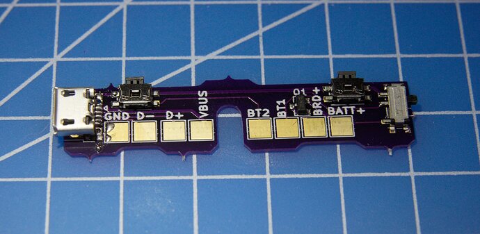
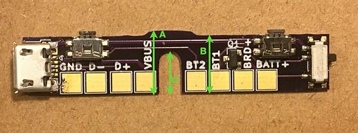
Ok, so this is the Proffie Flashback:

It’s sized to fit inside a graflex-style clamp, and provide an USB port on one end, and a switch on the other end. The switch can only handle 250mA, but a pFET is used to increase that to ~2A, which is enough for a Proffieboard.
In addition, the Proffie FlashBack has two buttons on top which converts the clamp card into a button.

A new addition is the bumps on the bottom, which are meant to be gently filed down until the board fits snugly. There is also a bump on the top which is meant to help the clamp card spring back. (Ignore the tiny bumps, they are just manufacturing leftovers.)

Anyways, I’d like to verify that these will fit in actual hilts out there. If you’re working on a hilt with a graflex style clamp and is interested in a free FlashBack, write a comment below.

1 Like

I recently got a graflex 2.0 new in box from a friend, no doubt long buried in a closet. I’d be interested. Do you need a full install, or just a quick wire- up of the board to see how it sits? I’m willing to try both PTFE and silicone.

I am working on builds with control boxes, but they are not Graflex-style clamps… but I’d still like to try this out. One is the right width but a little shorter (ronin), one is a little shorter and a little narrower (kanan jarus), and one is just way too small (depa). Can you share the dimensions? I also have a few re-work projects for the future (e.g. luke v1, obi 3.5)… so I am planning to order ~5 of the Flashback’s.

I’m actually already doing some testing and design work that I am using a graflex clamp for, so I have one handy. Not an actual install, but for testing something my setup would likely work well.

A quick wire-up is sufficient.

1 Like

What do you mean? Can you share links or pictures?

It’s 51mm long (switch sticks out ~1mm on one side)
10.5-11.8mm tall, depending on how much the bumps are filed.
It’s 3.6mm thick (at the USB port)

Then I’d appreciate the chance to try one out :slight_smile:

I’m in the UK which might be a pain for sending the board over, but I have some 89 Graflexes waiting to be built. I’d be happy to put one together as a guinea pig with this board if it helps.
:slight_smile:

That control box would need a completely different kind of thing I think.
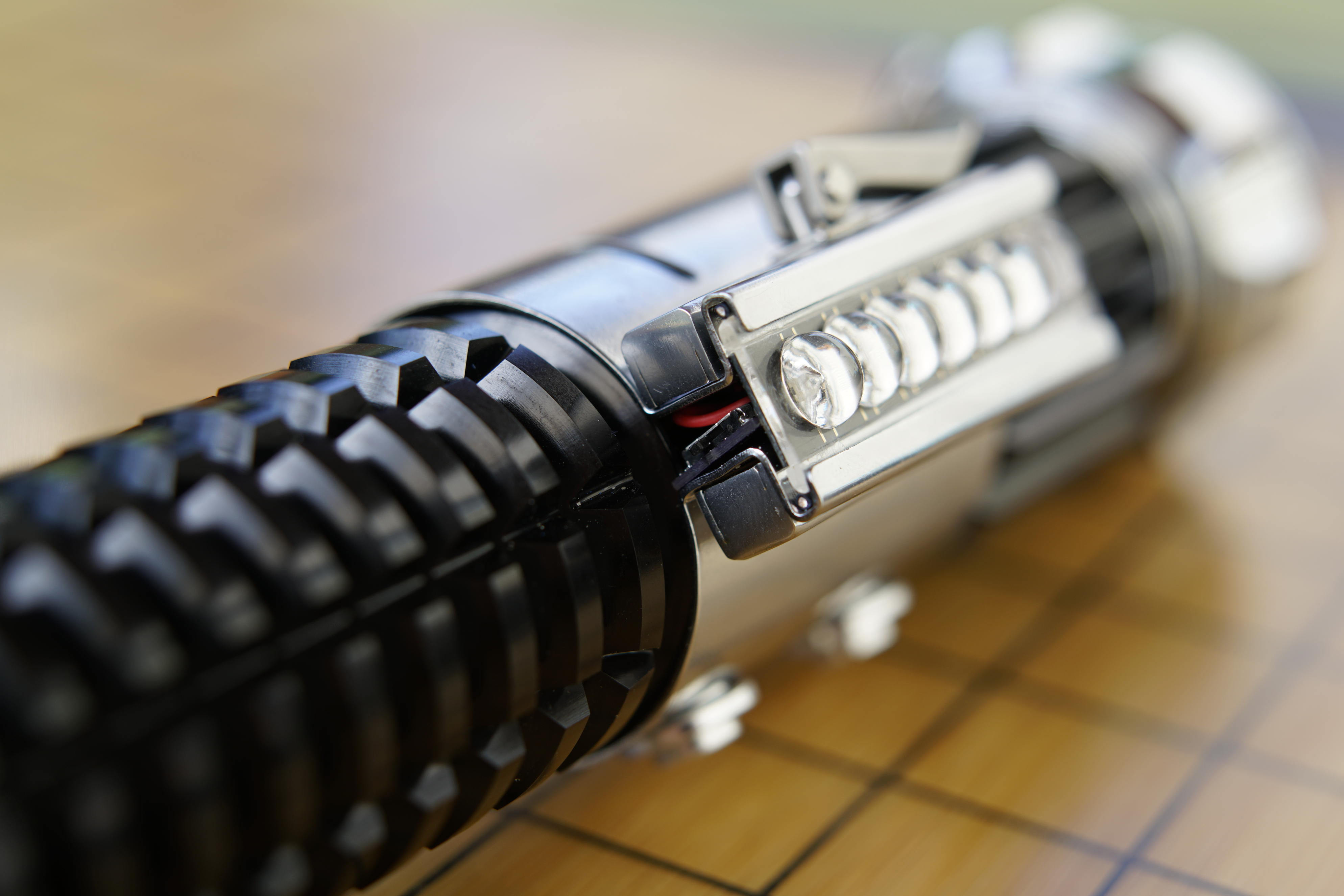
The FlexBack is meant to sit perpendicular to the clamp card, like this:

(This one is a little crooked, but it doesn’t matter, because I don’t use the buttons.)

Too long for any of my builds. It is even too long for my Obi 3.5 rebuild.
I really hoped it would fit in the Ronin with minor modifications–A combination USB, kill switch, and buttons… it was a dream solution.

`

The FlexBack is meant to sit perpendicular to the clamp card

`

I was envisioning the card parallel with the buttons on the side–much like the buttons on the Luke Hero/V1 design. But even with 3d printed extensions to the control box, the ito wrap would be in the way.

Ok, I’ve sent out a few of these for beta testing, so I should probably write up some instructions as well.

  • First step, file down any protrusions to make it smooth all around.
  • Step two, make it fit by filing down four bottom bumps until it fits nicely. The top bump should be touching the back of the clamp card. (Measure how much you filed down, I want to know.)
  • To make the buttons work, you’ll need your clamp card to be a little fatter around the middle. This means either filing down the sides a bit, or using some tape or hot glue to build it up a little. The idea is that the clamp will only hold the middle third (or less) of the clamp card, and the end parts can move relatively freely so that you can use it to press the buttons.
  • The board have three different functions: two buttons, USB and on-off-switch. Each function cane used or not used as desired. Each connection below will be tagged USB/BUTTON/SWITCH to show which connections are required for each function.
  • connect GND to GND or BATT- on the board. (USB, BUTTON, SWITCH)
  • connect D- to D- on the board/usb extender (USB)
  • connect D+ to D+ on the board/usb extender (USB)
  • connect VBUS to VBUS on the board/usb extender (USB)
  • connect BT2 to Button2 on the board (BUTTON)
  • connect BT1 to Button1 on the board (BUTTON)
  • connect BRD+ to BATT+ on the board (SWITCH)
  • connect BATT+ to + on the battery (SWITCH)
3 Likes

Initial height measured 10.72-10.74mm. Sanded down to 10.46 mm and the switches are clicking nicely with a basic clamp card, with no filing of the card. Bubble strip not so much I need to come back to that.

Is this a switched positive for the kill switch, so that BAT+ and BRD+ continuity is where to test it?

1 Like

Yes-but-no. Continuity won’t work properly since it’s going through a FET.
If you have GND and BATT+ up, you could hook up BRD+ to some sort of load (resistor, led, lamp) to test it.

1 Like

OK, here’s my report for the Proffie Flashback:

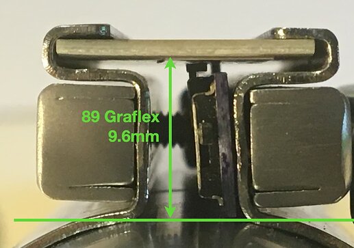
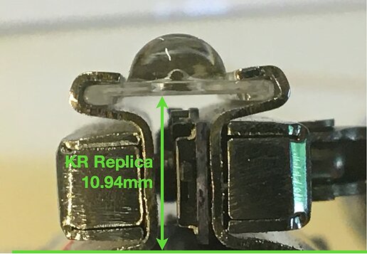
I’ve been working with an 89 Sabers Graflex hilt. It seems the switch box depth on the 89 is significantly less than that of a Replica.

Compare photos 1 and 2. Photo 1 is the 89 Graflex switchbox and photo 2 is a KR Replica (the first run he did with the slightly askew red button). These were both taken after I had modified the Flashback to fit the 89.

In terms of the modification needed to make the Flashback fit the 89, photo 3 shows the relevant measurements, the modifications to which are shown below:

Before Sanding:
A 11.75mm
B 10.75mm

After Sanding:
A 10.0mm
B 9.27mm

As you can see, in order to fit the 89, I had to skim the bottom of the Flashback almost back to the solder pads. I also had to elongate the centre slot slightly (measurement C). Unfortunately I forgot to check that measurement before I started, but I estimate I had to increase it by about 0.8mm. I basically went as high as I could without touching the trace running across the top of it.

I also had to shave the clamp card a little to make it work, though if using a Replica, this wouldn’t be necessary.

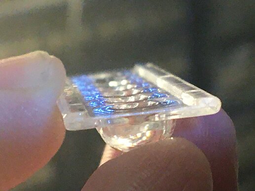
Whilst talking of clamp cards, I suspect that the Flashback may not work very well with a bubble strip for two reasons. Firstly the bubble strip is quite rigid, so may not provide the little bit of flex needed - especially when trying to do button combinations to press both at once. But secondly, the bubble strip has shoulders which limit movement in the channels. (See photos 4 and 2). I checked both the 89 strip and the KR strip and they were both the same and are around 0.7mm tall. You may be able to sand them away, but I don’t know how that would effect the structure of the strip. Maybe someone else has tried it?

Finally I haven’t got as far as wiring it up yet (I thought I had a chassis for this hilt, but when I went to build it it turns out I haven’t, so one has been ordered). However that side of it all looks pretty self-explanatory so I don’t think there will be any revelations there. The only thing people may wish to note is the fact that they would need to drill a hole or cut a notch out of the front section of the hilt under the clamp for the wires to pass through. This may also have a bearing on the type of chassis selected for an install that includes the Flashback.

Hope that’s useful.
:slight_smile:

3 Likes

Very nice details. My measurements would be equivalent to “B” in you photo, with the bumps on the bottom remaining and included. I never sanded the top bump. The graflex 2.0 has a tall clamp!

I wonder what the height of the vintage clamp is…

1 Like

For the bubble strip to work, you would probably want something behind it, otherwise the buttons won’t reach. Handling the lack of flexibility might be harder, but it may be possible to use some hot glue or double-stick tape in the channels to get a “soft mount” kind of thing happening…

1 Like

I should point out that in my K4 hilt (which has a bubble strip) I don’t actually use the flexback buttons, since the hilt has two very nice buttons on the side already.

1 Like

Yeh, I’d be curious to know that as well. I’d kind of assumed that Khal being Khal, his KR replica would have been pretty close to original dimensions, but would be interesting to compare if someone had a vintage they could measure.

OK, test review part 2:

I installed the board in the hilt today and wired it all up. Everything works well in terms of the buttons and the kill switch, but for some reason the USB connect doesn’t work right. When I connect to a computer via the Flashback, it boots the board, so power is working, but the board remains invisible to the computer. If I bypass the Flashback and plug directly into the Proffie, everything works fine.

I’ll get a meter on it tomorrow (it’s late here now) but the only unusual thing I did was run two wires from the flashback ground pad - one of which goes to the Ground connector on the Proffie, and the other goes to the Ground pin in the USB extension. I’m guessing this shouldn’t make a difference in theory as both grounds get combined by the board regardless. but I may try snipping the Ground to the USB tomorrow.

But other than that, everything works well. :slight_smile:

1 Like