Proffie FlashBack

OK, I’ve been trying to trace the USB connection issue and I’ve found the answer:

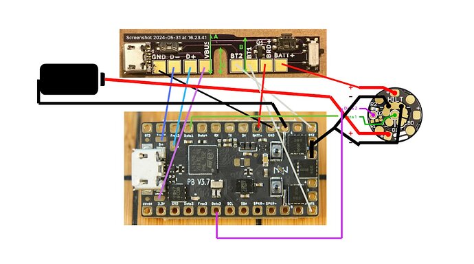
Prof, the USB Data+ and Data- on the Flashback are labelled the wrong way round. Switching those wires sorted the connection problem.

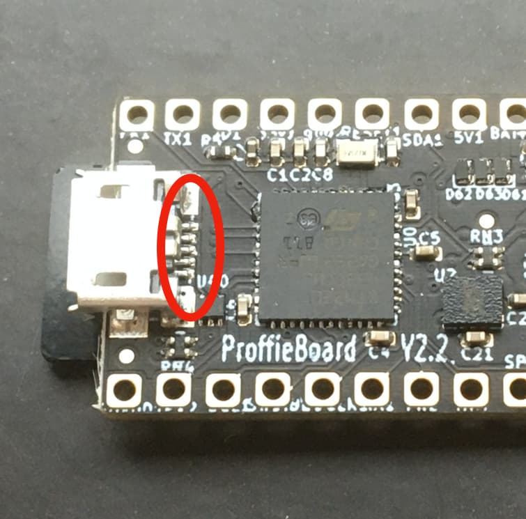
And in case anyone thinks I must have got the wires wrong at the micro USB end, the final working setup means when you check continuity between the Flashback Data- pad and the Proffie USB solder pads (see photo, circled in red), you get continuity to the middle of the five Proffie pads. But my understanding is that that middle pad is actually Data+, not Data-. Hence my conclusion that the Flashback labelling must be wrong.

The only thing that occurs to me that might account for it is if the convention for Data+/Data- works the same as TX and RX (Transmit and Receive), where TX on one board connects to RX on the other and vice versa. But I didn’t think that was case with anything labelled as a positive or negative.

Anyway if you were to go into production with this, I think that would need to be made clear to most people.

My only other thoughts regard the fit which was detailed above. As mentioned, height was a bit of an issue on the 89 hilt as it seems to have a shallower clamp box than replicas or vinatges. I managed to make it work on mine, but having reduced the height of the Flashback as much as I possibly could, the only way to make it work was to then sand down the clamp card to about half its normal thickness. This was tricky to do accurately, and I think would prove too onerous for many people.

It would have been easier to sand down the bottom of the Flashback more, but two things prevented this: the location of the square solder pads and the location of the USB socket.

Therefore the only way I can see that might make it easier on hilts like the 89 would be to set the buttons slightly lower which in turn would set the the rocker lug on the top of the Flashback slightly lower. There is just about room above the USB socket to allow enough movement on the clamp card for this to work, and you could still keep plenty of PCB on the bottom underneath the solder pads to allow easy fitting to replicas and vintages.

Hope that helps, and thanks again for giving me the chance to be a test pilot for this. I plan to offer this hilt for sale once I’ve done a video of it. :slight_smile:

I think you’re right D+ and D- are labelled backwards on the FlashBacks.
I will fix that.

It might be easier to just move everything else up actually. :slight_smile:
How much more space would you need though?

It wouldn’t need much. Comparing my modified clamp card to a new one, I shaved 0.25mm off the modified card thickness. When you push the modded card down, there is currently about 1.25mm clearance at full button press between the end of the card and the USB socket.

Therefore I reckon if you could move everything up (except buttons of course) between 0.5mm and 0.75mm, that would probably be enough, and should leave a little margin for any other hilts out there with even shallower boxes than the 89. And of course your plan to move components upwards would also mean taller clamp boxes like Replicas and Vintages would be unaffected - you would just sand less off the bottom of the pcb when fitting. Though to be honest, even if they were affected, building a little extra thickness for button pads on the underside of the clamp card is very easy with bits of tape, compared to having to shave it accurately in thickness.

If you do decide to do a run of them, I’d be happy to write up some installation instructions to include with them (or link to) if you think it would be useful.
:slight_smile:

Not directly related to installing it, but here’s a little tour of the 89 'Flex with the Flashback prototype board, aimed at the end user.
:slight_smile:

1 Like

Nicely done! Did I see that you used a male breakout microusb into the port, rather than trying solder to the board? Is that because it’s a 2.2? I’m going to try to solder via the above instructions right to a 3.9, taking the polarity labeling issue into account :slight_smile:

Yeh it was a 2.2 and as there was room for the connector in the chassis it just seemed like the easiest solution. The only thing to watch for doing it that way is to run the Flashback ground to either a ground pad or battery neg rather than wiring it into the USB extension. All the grounds are linked anyway (I checked), but I didn’t like the idea of the Flashback ground for switches and the kill switch FET being dependent on the USB being plugged in. As such, you can actually get away with just three wires going to the USB extension plug.

1 Like