So I just finished wiring up my neopixel Proffie V2.2, tested the wiring at several different points, everything seemed to be good, powered up fine with sound, soldered everything up, placed the board in the chassis and now nothing happens when I turn on the killswitch. I start looking for shorts, try to check the continuity between the 3.3V and GND pads as the Getting Started with Proffie document states and instead of the long beep a multimeter normally emits when detecting a closed circuit, it beeps once. It even does this when there’s no wire connected to either pad.
My board visually looks fine, I didn’t see any smoke or smell any burning so I don’t think it’s fried, there’s no visual shorts that I can see, any help or ways to go from here? I know I’m not the cleanest installer in the world, but nothing actually looks damaged or shorted here to me. My computer still reads the board just fine both in the IDE and when browsing the SD card files.
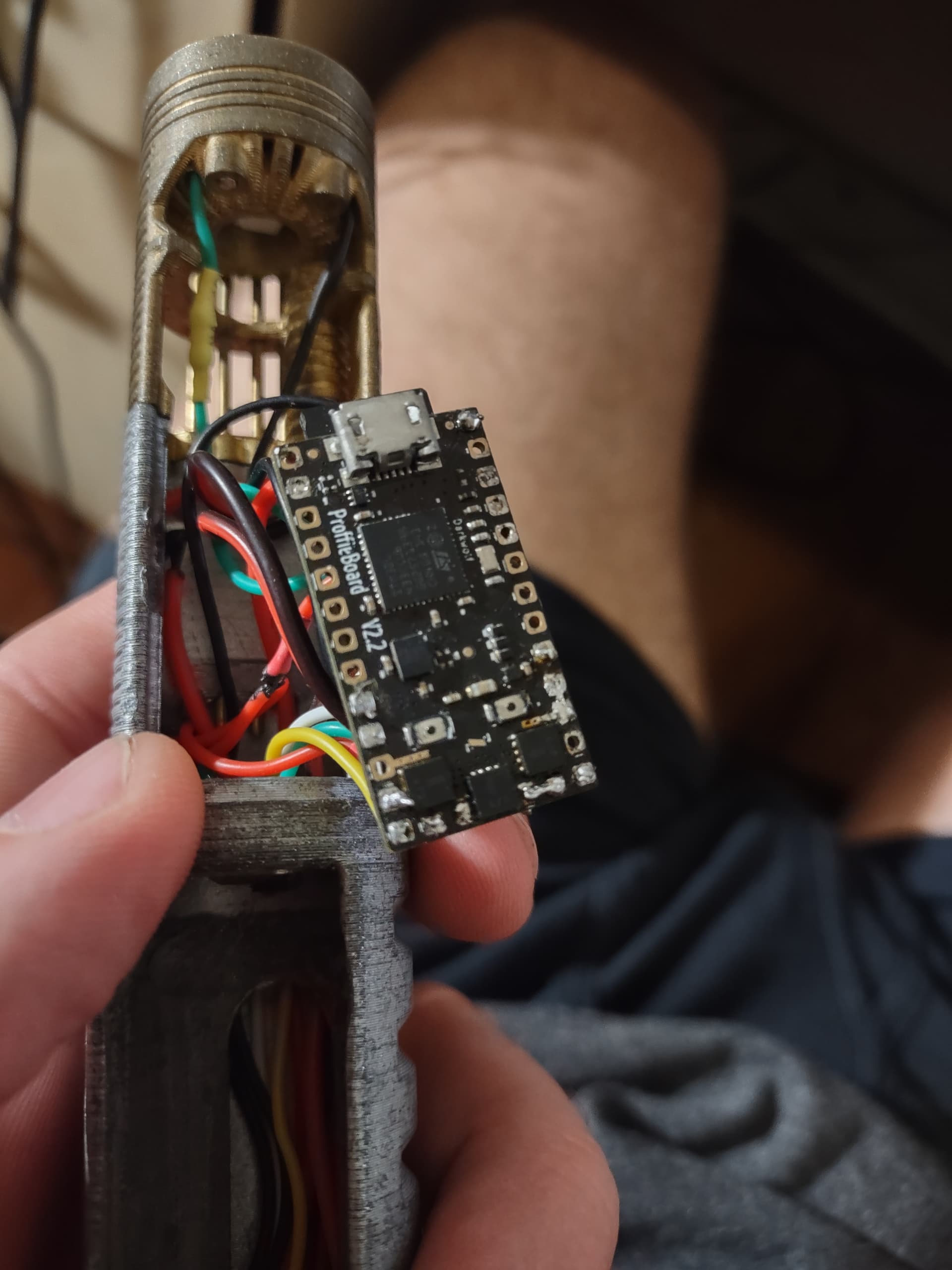
Check continuity on the kill switch and button(s). I’ve seen both randomly fail once wires are stressed and even the little metal rocker in the switch come loose once pressure was on the kill-switch shell. Fill in the rest of your solder points, you don’t want divots where the solder isn’t secure through both openings. Finally take a closer look at that solder near the mosfet to be sure nothing is touching and shorting out at the mosfet leads. Check both sets of mosfets, here’s a reference.
I checked the resistance between BATT+ and GND, I’m getting like .16 kohms, so something isn’t right there. Would that pretty much confirm the short is between those two pads, disconnect the wires, clean up the pads and re-solder them?
@A_Rogue_Child For button/kill switch continuity, you mean testing between LED 4/5/BATT+ and BATT-?
Might just be the angle, but some of those pads look a bit messy. The one near the FET at the bottom left (LED 6?) has some bits poking out, for example. And speaker -.
Are you sure it isn’t booting? Have you tried a blade? Maybe a speaker wire had a tug in the course of the install, stopping it (the speaker) from working, even though the rest of the saber is fine.
That was pretty much it. A slight issue with the speaker and now it powers on…except now…
My AUX button is completely unresponsive (two-button saber). PWR button works fine, saber ignites and retracts, no issues there, but it’s that switch does nothing.
The switch has a common negative with the PWR button, it’s connected to the correct pad on the board and my config defines it as such, I get continuity across the BUTTON2 and GND pads regardless if the switch is being pressed or not. I tested a spare, new switch across those pads and same issue. Could there be an issue with the BUTTON2 pad, could I rewire that BUTTON2 lead to BUTTON3, alter my config file to reflect and hopefully fix the issue?
What could cause continuity between those pads, a bridge between pads somewhere or other components of the board? Switch wiring isn’t exactly necessarily complex (despite my problems lol)
Check your wiring. If you have spliced one wire from each switch together and then soldered that to AUX instead of Ground, that might give the symptoms you describe.
That spliced common wire is attached to GND, not AUX. PWR works with its other lead attached to Button1, the AUX button’s other lead is attached to Button2 and does not.
The bit that doesn’t make sense is if you’ve correctly specified two buttons in your config - both at the top of the config file and the bottom - and you have continuity between the AUX pad and Ground pad, then the board should read that as the button being held down. In other words it should be doing all sorts of weird stuff like trying to change fonts while it tries to enter the volume menu while it tries to enter colour change etc. etc. depending on what Prop file you’ve used.
The fact it’s doing none of that makes me think your config might be set for one button operation.
Also test the voltage (not continuity) between the AUX pad and the ground pad. It should be at, or very close to, 3.3 volts and should be solid and not wavering or fluctuating. Try it with the aux wire still connected, then try disconnecting the wire and see if it changes.
Just posted it and I believe it is configured for two buttons unless I’m misreading it.
I’m not getting any voltage across Button2 and GND with the switch connected, I’m getting a steady 3.3V across Button1 and GND. I’m physically inspecting the wiring connection and there’s nothing that seems to be out of place.
No problem.
Although I can’t see anything obviously wrong with the button setup.
How about continuity between the AUX pad and one of the pads next to it (LED 4 and 6)? Obviously there shouldn’t be any, but a short would cause it. Any loose strands on the underside of the board beneath those pads that might be upsetting things?
Other than that, I confess I’m a little stumped.
No shorts there, I tested some alligator leads on Button2 and the GND pads and I’m pretty sure I was able to confirm that it’s just a mechanically bad switch. Saber Armory finally got some replacement switch PCBs in so I’ll wire those up and hopefully be able to confirm.