If you made a bunch of disk-shaped PCB’s ~9mm in diameter, you could make a stack that would fit inside the normal blade foam.
19 AWG solid copper wire running through the middle for 15 AMPS of current, and 26 AWG for the data signal. It would be very flexible and hard to break. Something like this:
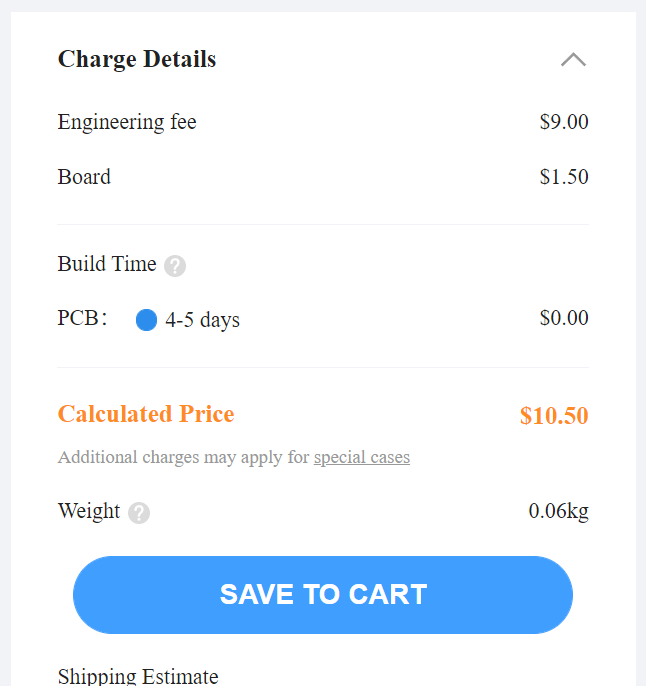
Interesting idea. The 20 cents is for a blank PCB though, right?
The assembly seems like a pain though. The PCBs will need to be threaded onto the wires and soldered individually, sort of like making an old-fashioned LED string blade, and the data wire would be even harder since it needs to be a separate wire in between each PCB. (In your diagram you have all the DINs connected together. The connection to the next PCB has to come from DOUT on one of the LEDs though. Personally I would prefer to have each LED individually addressable though, which means connecting DIN->DOUT everywhere.)
What’s even worse is that if you screw it up somewhere, fixing it is going to be pretty difficult.
One possible way to improve upon this concept would be to make the PCB double-sided, with 3 LEDs on each side. (60 degrees shifted) This could reduce the amount of assembly needed and also potentially cram a few more LEDs into the blade AND lead to less shadowing.
I wonder if maybe it would be simpler to use some sort of stackable headers for this. It would add to the component cost, and the PCBs could possibly come apart, but it would be super easy to assemble, and super easy to replace a piece if it was to go bad.
I really think assembly wouldn’t be that bad though…you could cut some 3 mm silicone tubing and put it around the power wires to help with spacing. It will be a pain to solder 200 boards though.
Ideally you’d test each pcb before assembly. Maybe with a simple pogo pin setup connected to an arduino.
Are you talking about having three searate data signals? What is the benefit when the blade only has one data pad on the shtok connector?
Yes, but it might tax the OS a bit.
The maximum frame rate would be 53 FPS, which should be good enough.
If the blade styles are too heavy, I can implement something that just duplicates the values 3 times to speed things up.
I don’t suppose these pixels support 1.6Mhz data rate? That could potentially double the frame rate.
I have a blade for my K4 saber which has 529 leds in it. It works pretty well with ProffieOS 5.x, but I expect it to work even better with ProffieOS 6.x:
I also have plans to build a quad-blade using higher density strips:
Even with the stencil and shipping that comes to 10 cents per board. The LED’s are the expensive part. Even buying 600, they are $0.299 each. So, the blade will cost ~$220 all told. Still, I think I am going to make it anyway.
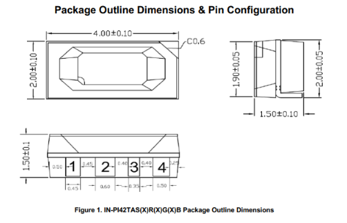
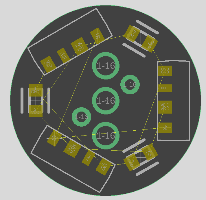
The center hole is GND. Both large holes on either side are VDD. One of the small holes is DIN, and the other is DOUT.
Every PCB is rotated 180 degrees, so that DIN lines up with DOUT every time. Since VDD is on both sides of GND, the PCB will still slide over the power rails when rotated. As a bonus, the lighting will be more even because the LED’s are on 120-degree spacing, and when rotated 180-degrees, an LED is pointing in the direction missed by the boards above/below.
Finally, I’m going to 3D-print some removable spacers to set the gap between PCB’s when soldering them to the power rails.
You still only need two wires for power with the way I showed. The center one is always the same, and you only need one VDD wire. There just has to be a hole on both sides when you rotate.
If I have to make 300 PCB’s, they’re one-sided and going in batches of ~100 in my toaster oven…
Double-sided would be great though in terms of pixel density. These LED’s are really promising I think, being only 2mm tall. I’m getting a 0.8mm thick PCB.
I would seriously consider having someone else do the assembly of these.
Unless you have a pick-and-place machine, this will be an insane amount of work.