Multi pin chassis connectors

I am in need of a (at least) 10 pin chassis connector. It is a cross guard, so one main blade, 2 small blades and 2 buttons, all past the connector.

I need: btn1, btn2, gnd, d1, d2, d3, led-1, led-2, led-3, batt+

I have found 3 options:

1 - TSM removable chassis connector

https://www.etsy.com/listing/1531048924/tsm-removable-chassis-pcb-connector-set

This one is a bit strange, many pins, and some don’t make sense, four 5v pins?

The seller says that it is rated up to 15 amps, but I am skeptical due to how small the pins must be. I could tie a few together to make sure there is more copper for the high amp lines.

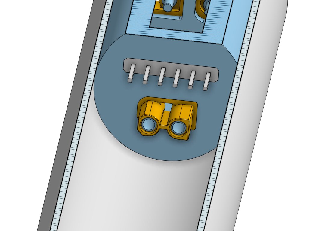
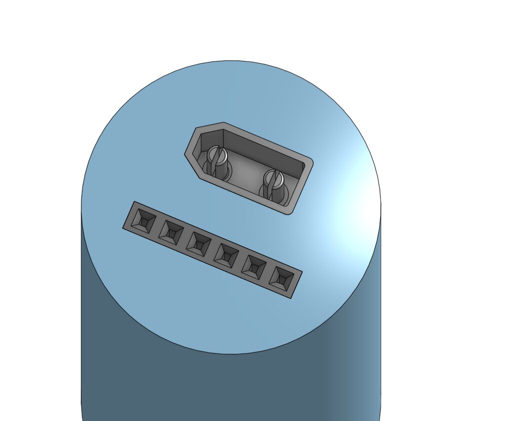
2 - Shtok 10 pin chassis connector

I would be using each pad/pin for discrete use, so not really how its intended. I would have to get a hold of one to test. It is rated to 15 amps as well, but that appears to be if you use both sides for positive and negative bring down the connection count to 8.

If I used “shared power pins”, I guess that would bring my connection count down to 8. btn1, btn2, gnd, d1, d2, d3, batt+ and all led-. Would that work?

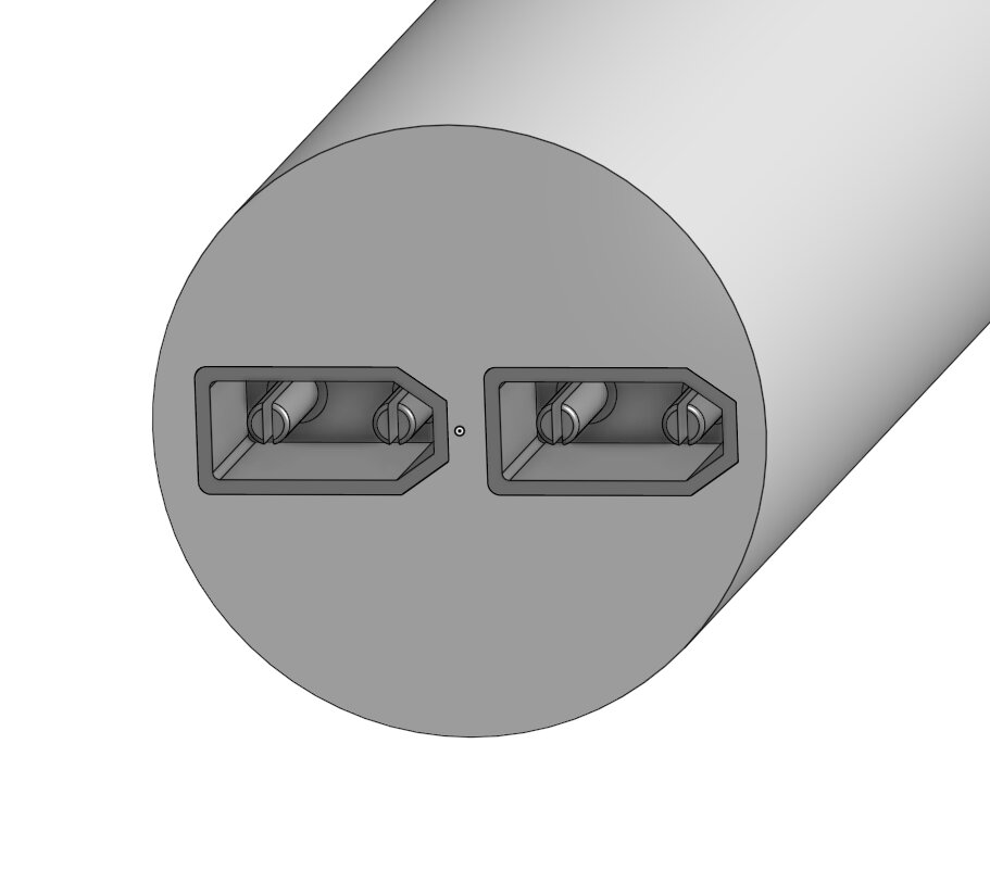
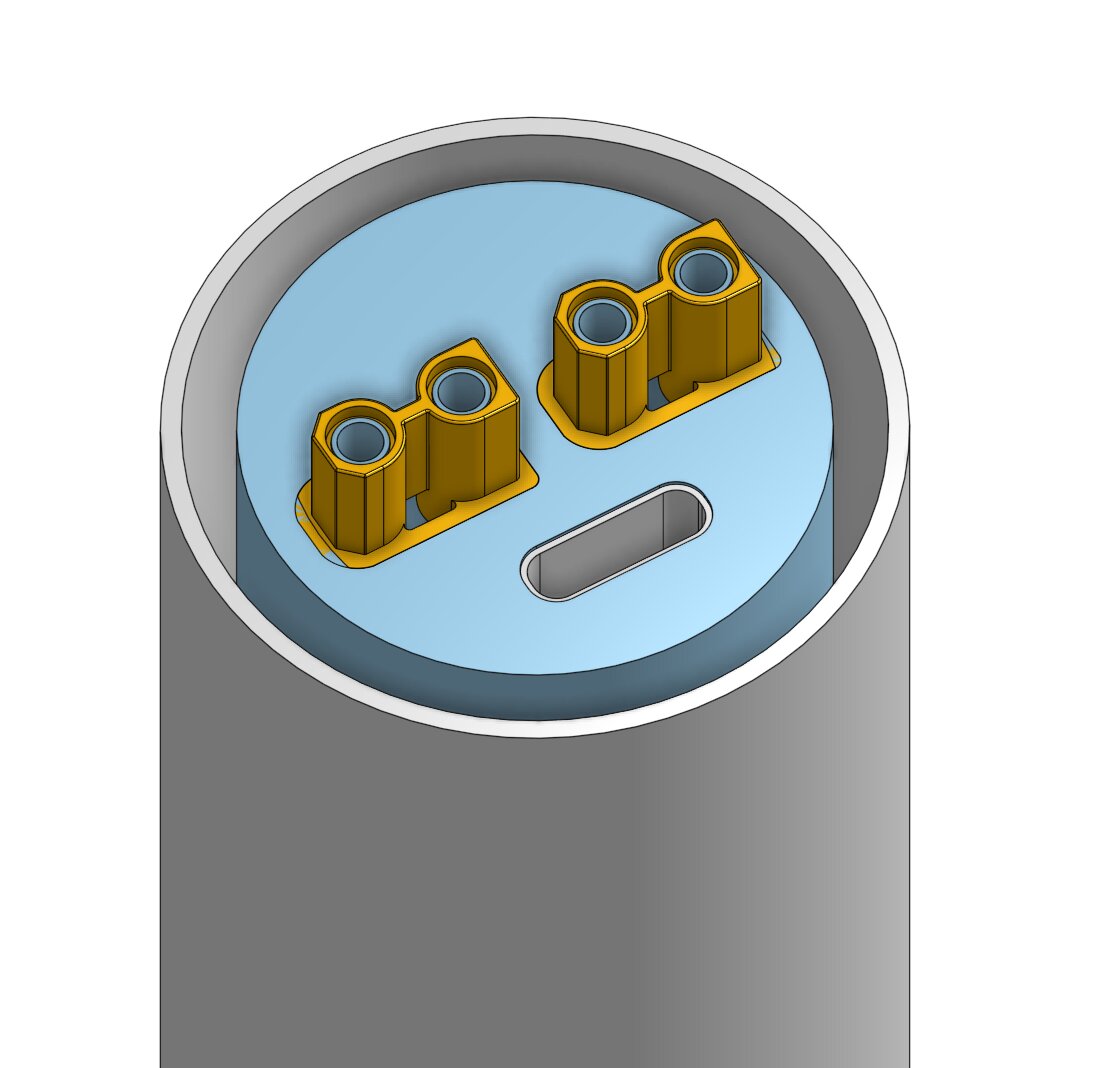
3 - 89sabers chassis set

https://www.aliexpress.us/item/3256806756924385.html

This has 13 pins but doesn’t list the amp rating. The pins appear pretty beefy and are directly connected to the solder joint. It’s what 89sabers uses for the same situation in their own sabers, so I assume it would accomplish the amp rating.

4 – design my own? I like this idea, as I like to design things and implement them, but I have not done pogo pin pcb’s. I think I could figure it out.

Can I get your opinions on these ideas? Has anyone made a chassis with 10 or more removable pins?

I found this post Best way to solder a small 10 pin connector - #10 by Maff76 which appears to have at least 10 or 11 (depending on how many oins are + and -), but looks a little precarious to me.

You can save one pin by ditching the switch ground and instead have the switches short to Batt+, which will already be available on the neopixel connector, then just change the config to suit.

I would also use just two data lines - one for the main blade and the second one split and shared by both side blades, as I imagine you will always want each side blade to do the same thing.

That gets you down to six rings (Btn1, Btn2, D1, D2, Batt+, LED neg) which gives you a few more options as it means you could use either of these:

If you use the 7-pin, you could then add blade/chassis detect as well by jumpering the back of the pin connected to Blade Detect to the LED neg pad - then when you insert the chassis, it reads that contact closure which tells the system the chassis is inserted.

Lots of options - hope something in there is useful. :slight_smile:

Oh, I didn’t know you could do that! Can you point to some more info, like what to change in the config?

I like the idea of having different animations, like in an unstable blade, but otherwise your right. They would be the same 95% of the time.

I had seen (and used a few times) both of those chassis connectors. Thanks for the help, I guess I just need to decide if I must have separate blades. :slightly_smiling_face:

2 Likes

I don’t think many people do know about it! :smiley:

All you need to change is the button setup right at the bottom of your config, like this:

//  Button shorts to GND (normal):
#ifdef CONFIG_BUTTONS
Button PowerButton(BUTTON_POWER, powerButtonPin, "pow");
Button AuxButton(BUTTON_AUX, auxPin, "aux");
#endif

//  Button shorts to Batt+ or 3.3 volt:
#ifdef CONFIG_BUTTONS
PullDownButton PowerButton(BUTTON_POWER, powerButtonPin, "pow");
PullDownButton AuxButton(BUTTON_AUX, auxPin, "aux");
#endif

:slight_smile:

3 Likes

Thanks!

A few more questions. If I enable shared power pins #define SHARED_POWER_PINS, and have led2 and 3 bridged, do I just use those for all blades? or should I bridge more pads?

BladeConfig blades[] = {
 { 0, WS281XBladePtr<132, bladePin, Color8::GRB, PowerPINS<bladePowerPin2, bladePowerPin3> >(),
    WS281XBladePtr<26, blade2Pin, Color8::GRB, PowerPINS<bladePowerPin2, bladePowerPin3> >(),
    WS281XBladePtr<26, blade3Pin, Color8::GRB, PowerPINS<bladePowerPin2, bladePowerPin3> >(),
    CONFIGARRAY(presets) },
};

I’ll link this in here also :slight_smile:

2 Likes

That works. Since your other blades are short they shouldn’t need an extra mosfet.

You could wire another one up if you want just to be Uber safe, but 2 should be plenty.

2 Likes

Maybe a stupid idea, but could it be possible to wire the two side blades in series and “sub-sub” blade the pixel connectors ?

Usually, yea, that would work data wise. But these are removable blades, so they have a 3 trace pcb. No way to get to the out on data, not to mention blades usually don’t have pads at the end.

You can chain together as many pixel segments as you want up to 20.
However, you need a data out from each segment until the last pixel.

1 Like

I didn’t know about this number. So is it 20 pixels, or 20 segments of pixels with a variable amount of pixels per segment ? Sorry, I am tired, I believe it is 20 segments with a var amount of pxl.

Yes I knew that, but I just realized now that a NPXL connector does not have a data out. :roll_eyes: (but i whish it had)

20 blades with varying pixel counts.

1 Like

^^ this ^^ Only 20 pixels would be a pretty bad limitation, considering main blades :crazy_face:

1 Like

If 20 turns out to be a limitation that matters, it could easily be increased in this file:

As I said, I was very tired last night, I had initially understood max 20 pixels in a row if they are linked together in multiple sub-blades . No, 20 blades is not limiting (yet). In fact this is the max I can think of:

  • main blade +2 for the NPXL connector (3 total)

  • cross guard blades +2x2 for the NPXLs connectors (6 total)

  • one green and one red little triangles (2 total) (but this could be one)

  • dual crystal chamber, one crystal & one marble (2 more)

  • plasma gate chamber with motor (2 more again)

  • accent ring in the pommel (+1)

  • accent ring for the speaker (+1)

  • two accents strips along the battery (+2)

  • another random accent ring somewhere, because why not (+1)

  • 2 led buttons (+2)

  • a secondary main blade +2 for NPXL connector (+3)

  • did I miss any ?

Oh cr@p, I think the total is 25 +/- 1 (I am tired again), so yes 20 could be limiting if I had the skills (I wish) to wire and solder that many (sub-) blades. :crazy_face:

Edit: I did miss at least one more: the Bluetooth “fake blade” (so another +1)

Edit2: the red bargraph thingy (+1 again)

What does this mean?
You’d have a staff with a crossguard in the middle?

I was just thinking “theoretically”, so no you would have a staff with 2 crossguards in the middle (makes it easier to impale yourself :rofl:), so that is another +6. I don’t think outside the box, I like to dismantle the box and make a new one. :upside_down_face:

I like staffs, but I like crossguard more, but I can imagine a staff that has an active crossguard when the second staff blade is inactive. Also, there would not be a pommel in a staff (so that is -1)

So first, I think there’s great recommendations you should go with in the other replies. BUT, if you wanted the crazy option then a diy connector could be fun. I haven’t built it yet, but I’m planning a similar chassis connector. My plan is to use an xt30 for the heavy power, then DuPont/header connectors for all the rest. Those don’t need to carry much current, and they’re very compact. And most of all, that setup would be cheap. You would need a 3D printed to do that right.

Just a crazy idea, but I think it’d work.

Also: I wish there was a master catalog of all the possible parts like this for when I’m looking at options for possible builds.

So, will you have to unplug it to remove the chassis? I am shooting more fo the pogo pin type.

There is this thread

There is a link to a zip of some common components. I have some more to add, but still working on them.

Let me find a concept pic…

BOTTOM OF BLADE
2x XT30’s (positive, negative, signal, positive return-path)

TOP OF HILT
Using 2x XT30’s… optional USB-C for separate charging plug.

INTERNAL HILT CONNECTOR
This is the XT30 (for power) and the dupont connectors (for buttons, accents, etc)

INTERNAL CHASSIS CONNECTOR
This is the top of the chassis, which (hopefully) inserts right into the hilt. I’ll have to experiment to see if I can get this to be not hard to remove. Definitely not as elegant as POGO, but I think it could still work well.

2 Likes