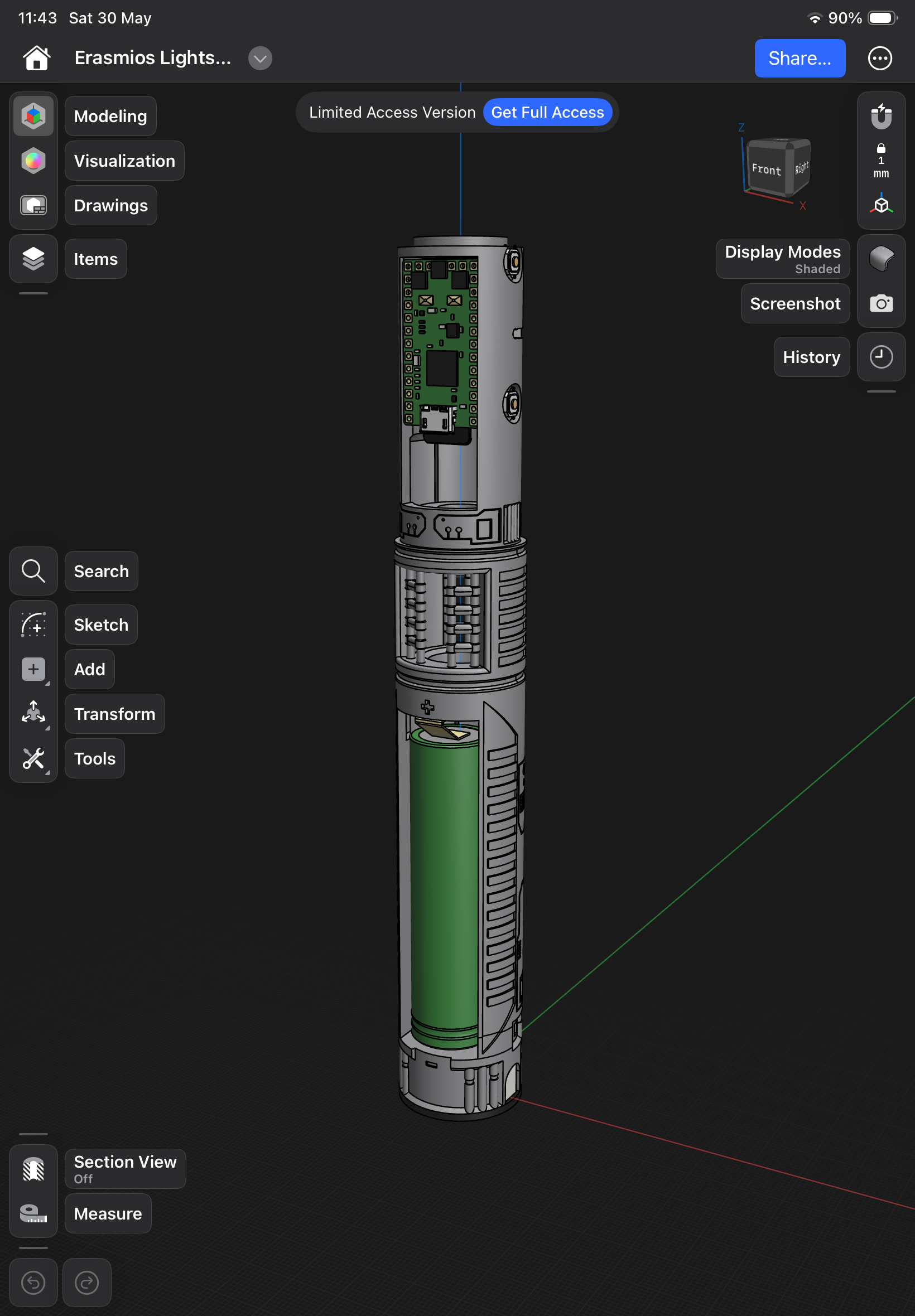
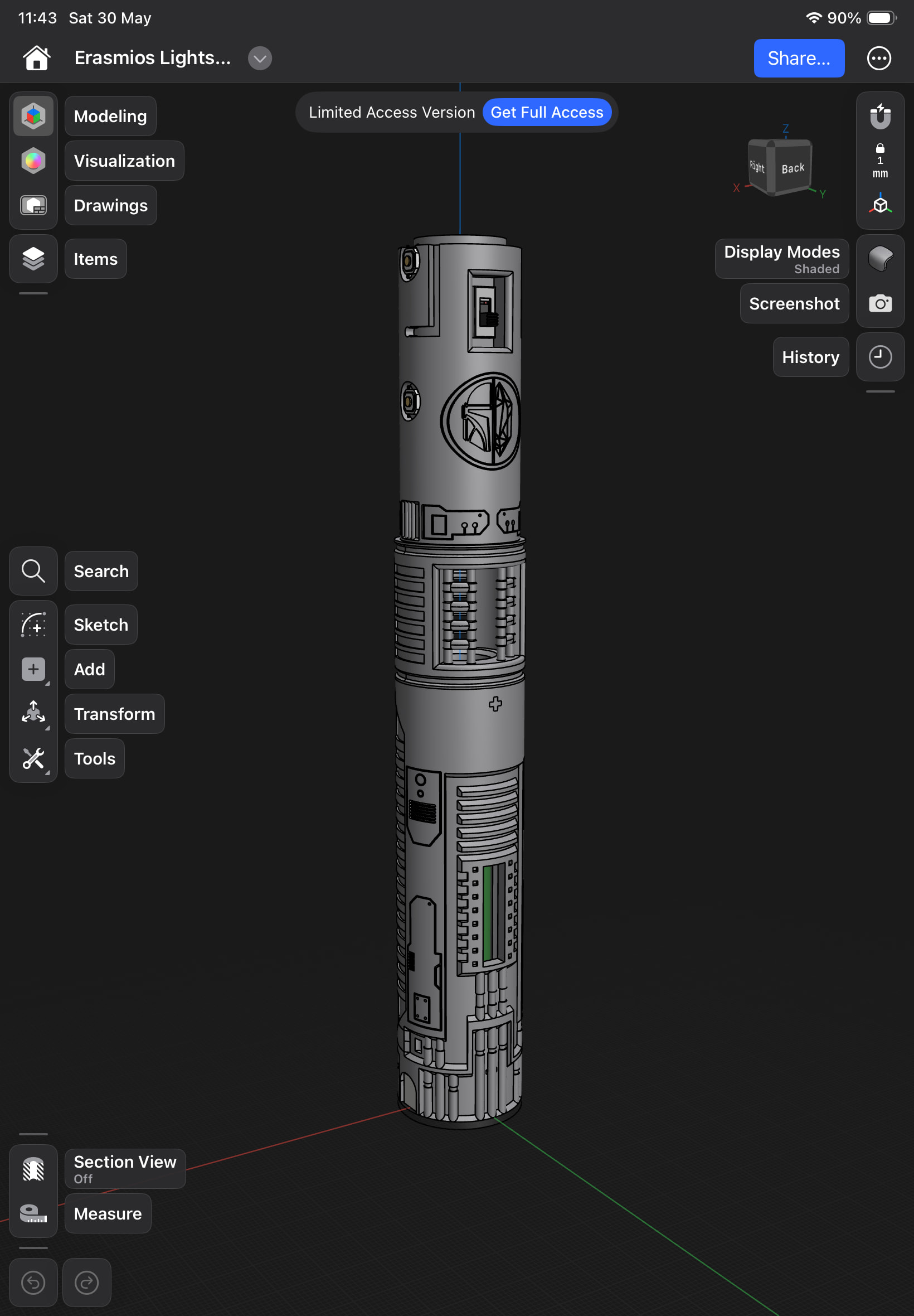
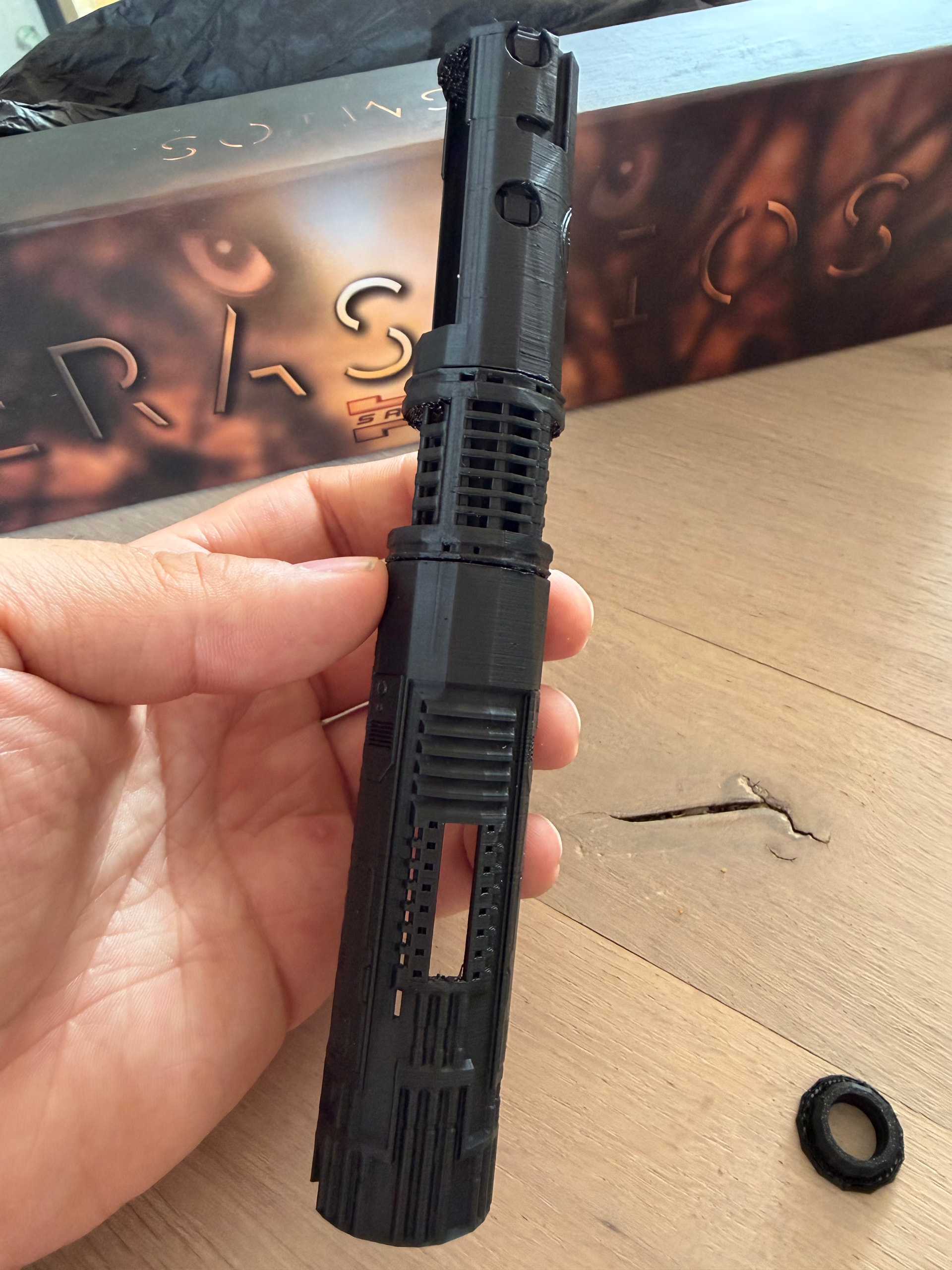
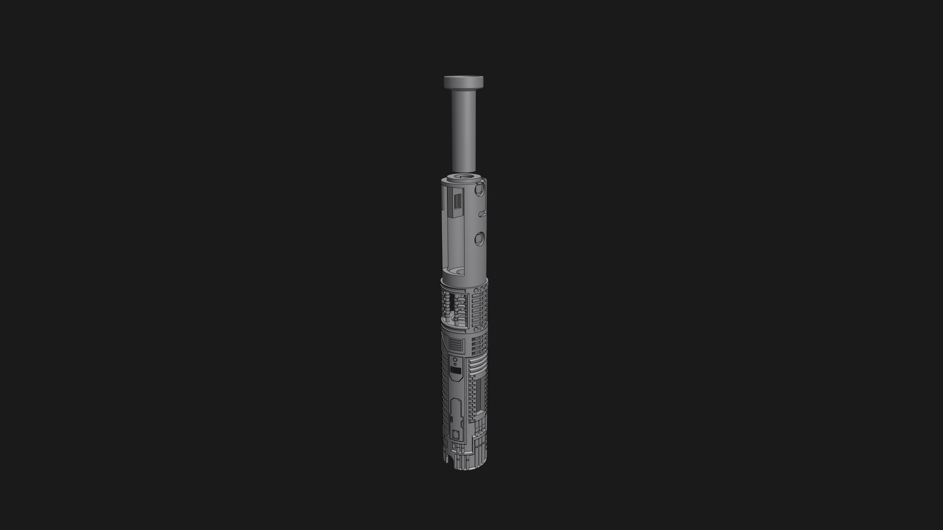
Last week I ordered the KR Sabers Erasmios Empty hilt and I’m currently designing my own chassis for this. It’s still in the design phase but I wanted to show you guys because I was excited about it.
This is my first attempt to design/build a chassis from scratch. I used Shapr3D in case you’re wondering.
I ordered pretty much every component from the ECO-MAX install kit separately, except for the motor. I’ve also ‘upgraded’ the speaker to a S.O. Dark Side Extra Bass speaker.
I’m planning on using a Quartz crystal as kyber crystal, but I still need to buy one that fits.
Looks fantastic, I just did this install myself with their chassis since I ordered that as well. Never have I had as much issue with it as that little thin neck piece and trying to give myself enough wire and space to solder, but fit snug without gluing and having them push the pieces out.
May have to bother you to see if you’d make a chassis for me for my couple of Ultrasaber Grand Master hilts. Lol
The Grand Master is a fine looking hilt. I really enjoyed designing the chassis so I’m probably up for designing a second one after I finish this project.
As I’m new to the whole “designing a chassis” and especially to “commissions”, I’d have to figure that part out
Anyway, you can DM me about the details and we can probably figure something out if you still want
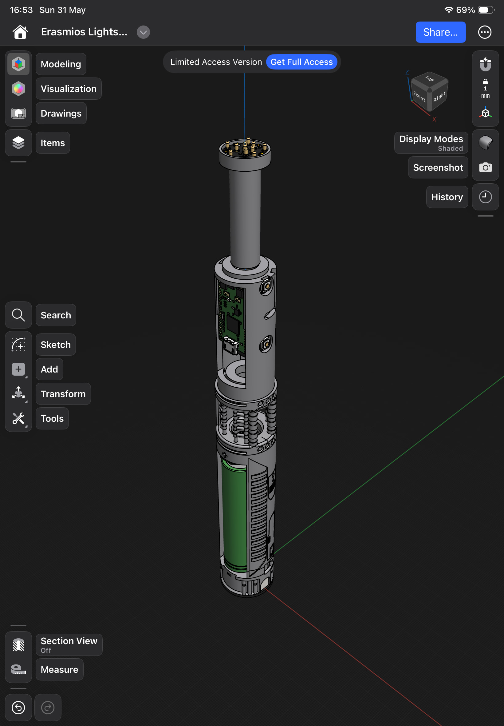
I changed up the design a little bit again. (2 times actually)
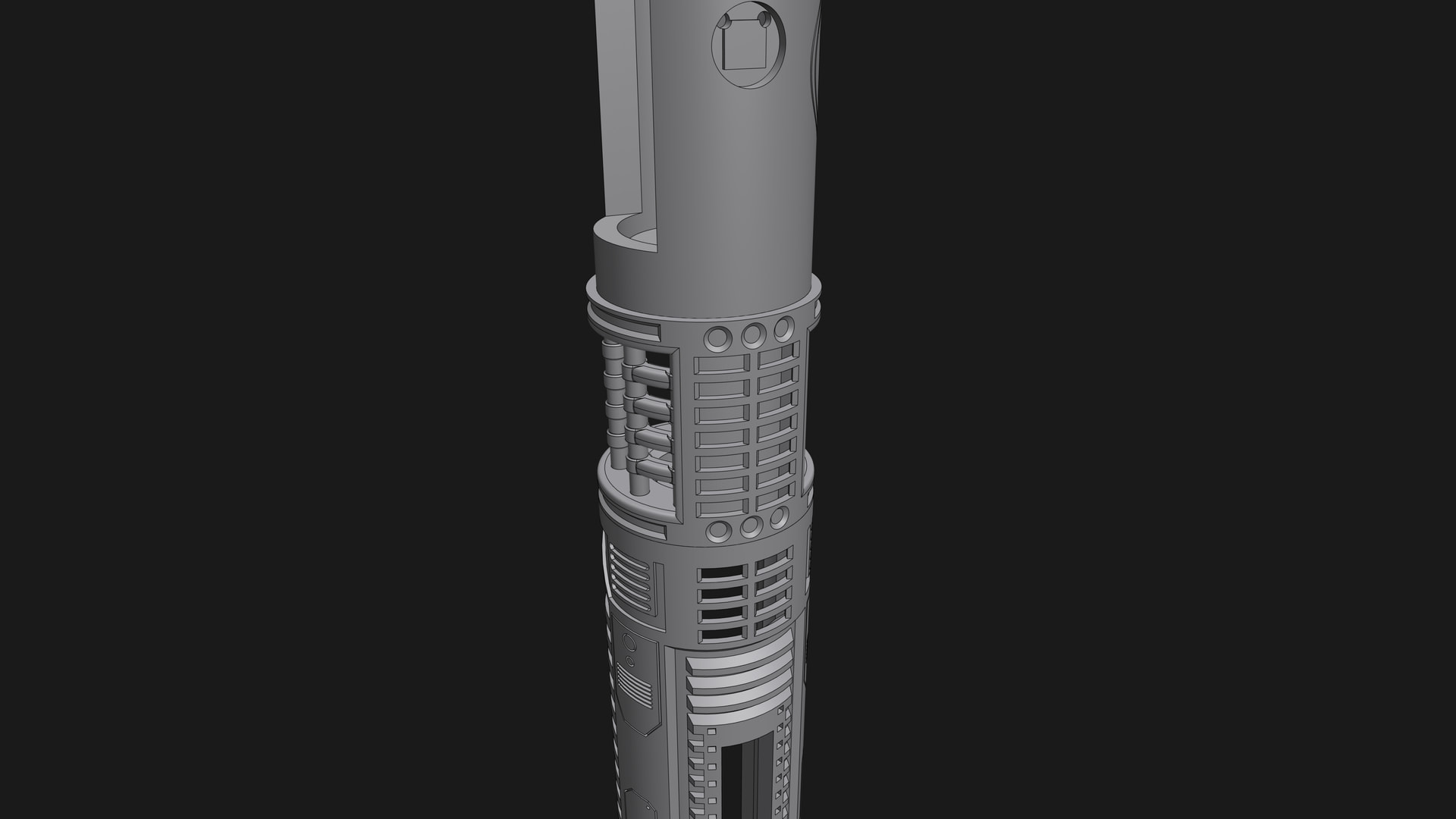
First of, I noticed the orientation of the 3 parts were not in line with the hilt.
A bit opening was on the left.
The OLED was on the right
The clearing between the proffie board and the kill switch vas very little.
After these changes I did a test print. But because I was using the free version of Shapr3D, I was only able to get a ‘low-res’ export sadly. However, for a test print it seemed fine.
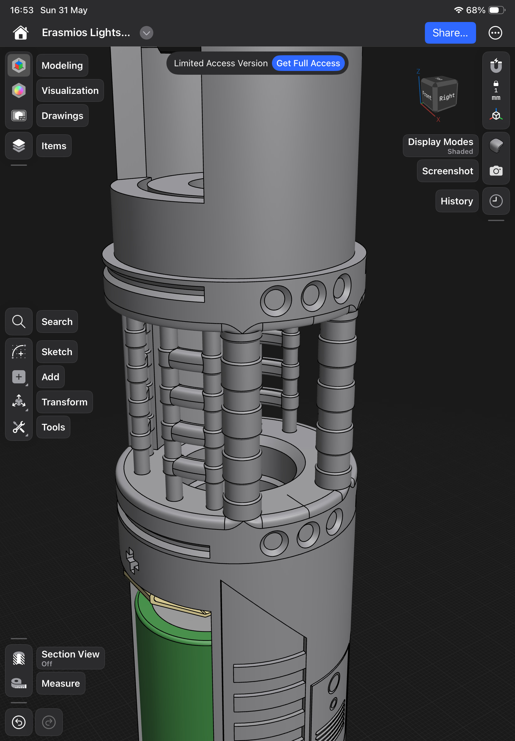
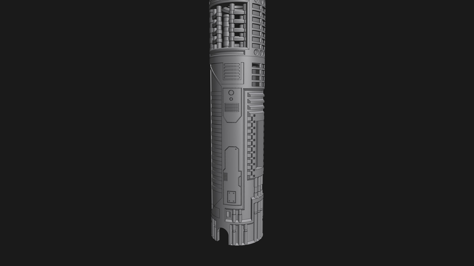
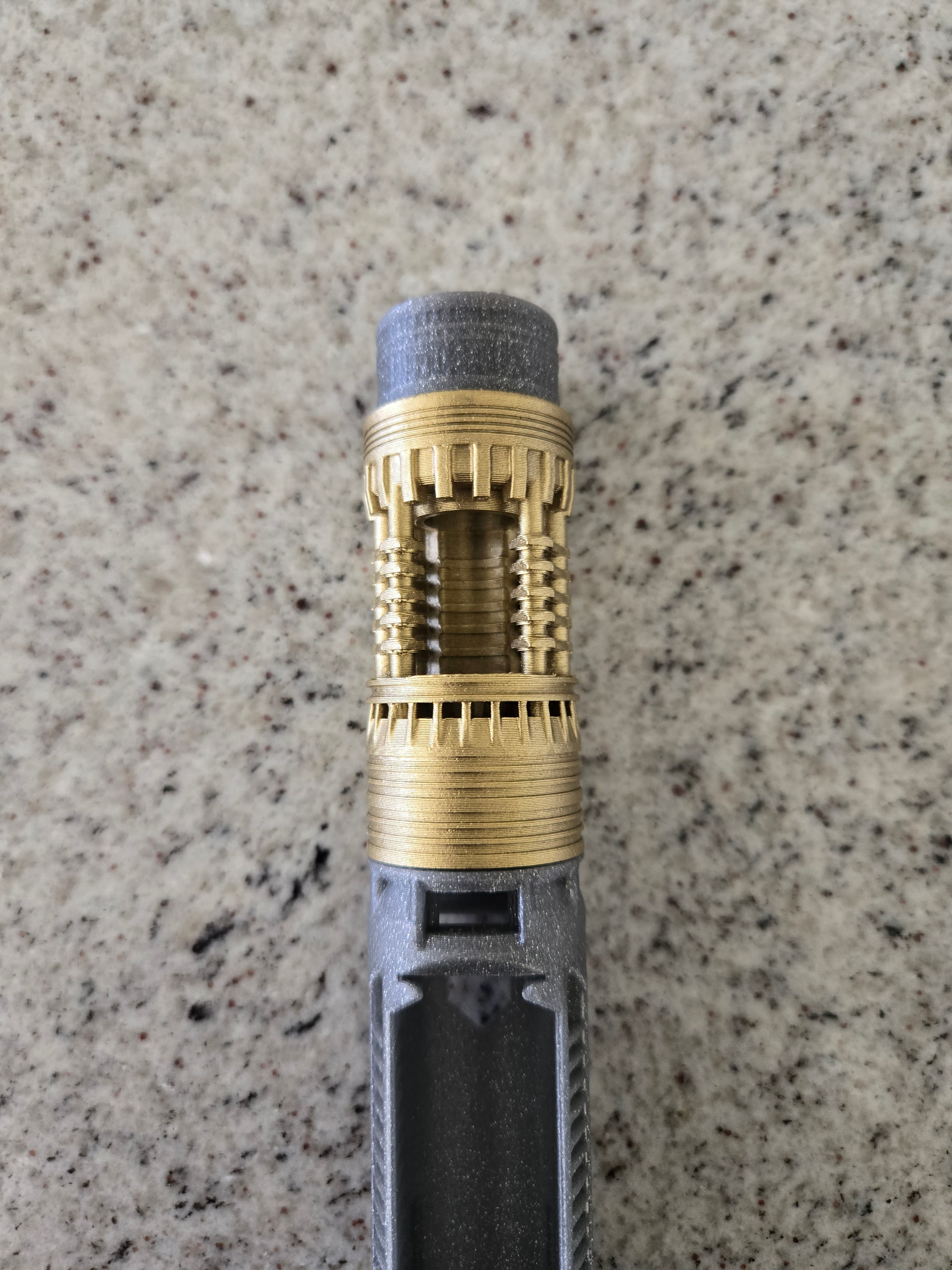
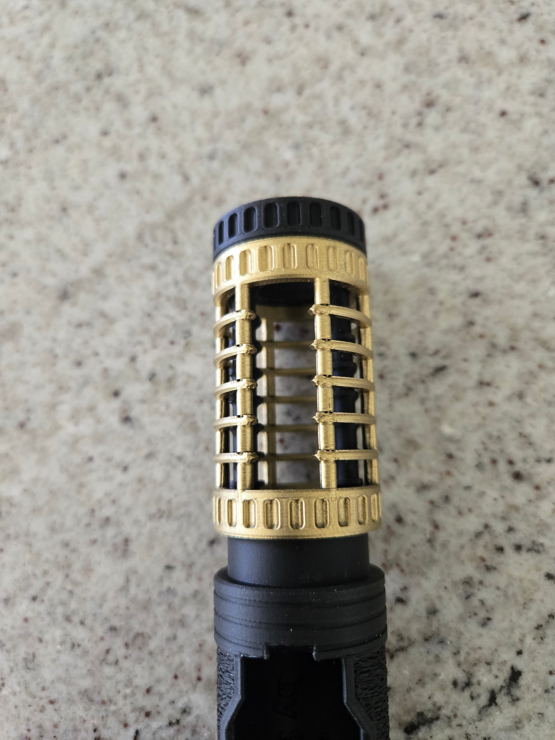
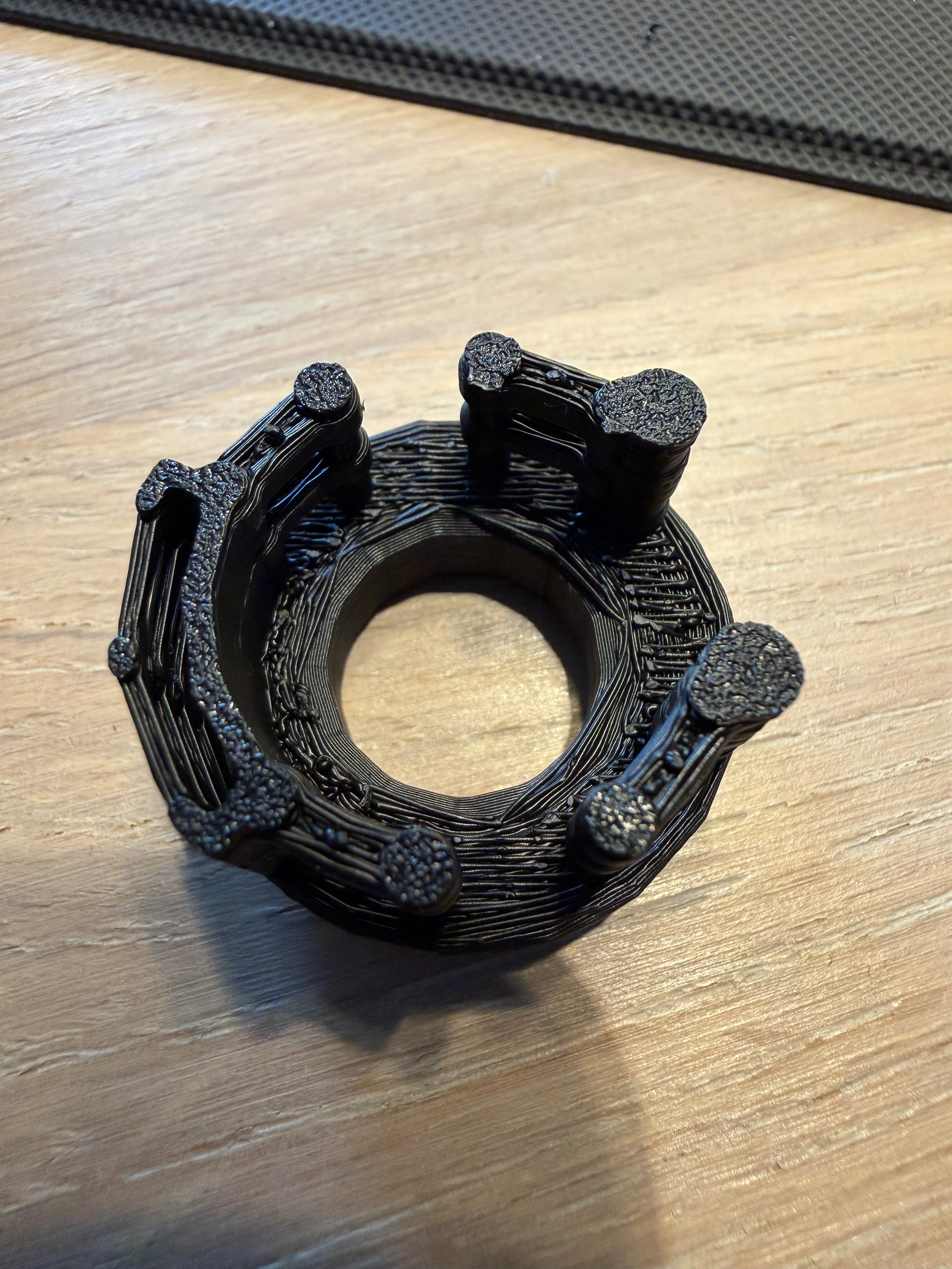
Here I found out, some of the details were not really good, and the wire hole had gaps (as you can maybe see in the picture above). However, I kind of liked the fact that the wires going through the crystal chamber were visible, so I added that to the design. All other issues I resolved.
Since the first test print was in such low poly, the button part was to small and did not stay in the retention screw slot thingy. The actual design is the correct diameter, so most likely with the ‘paid’ version, I’m able to export the high-res file.
The final version will have a different color crystal chamber, but I currently don’t have any ‘brass-like’ colors. So I’m thinking of using a dark-ish brown
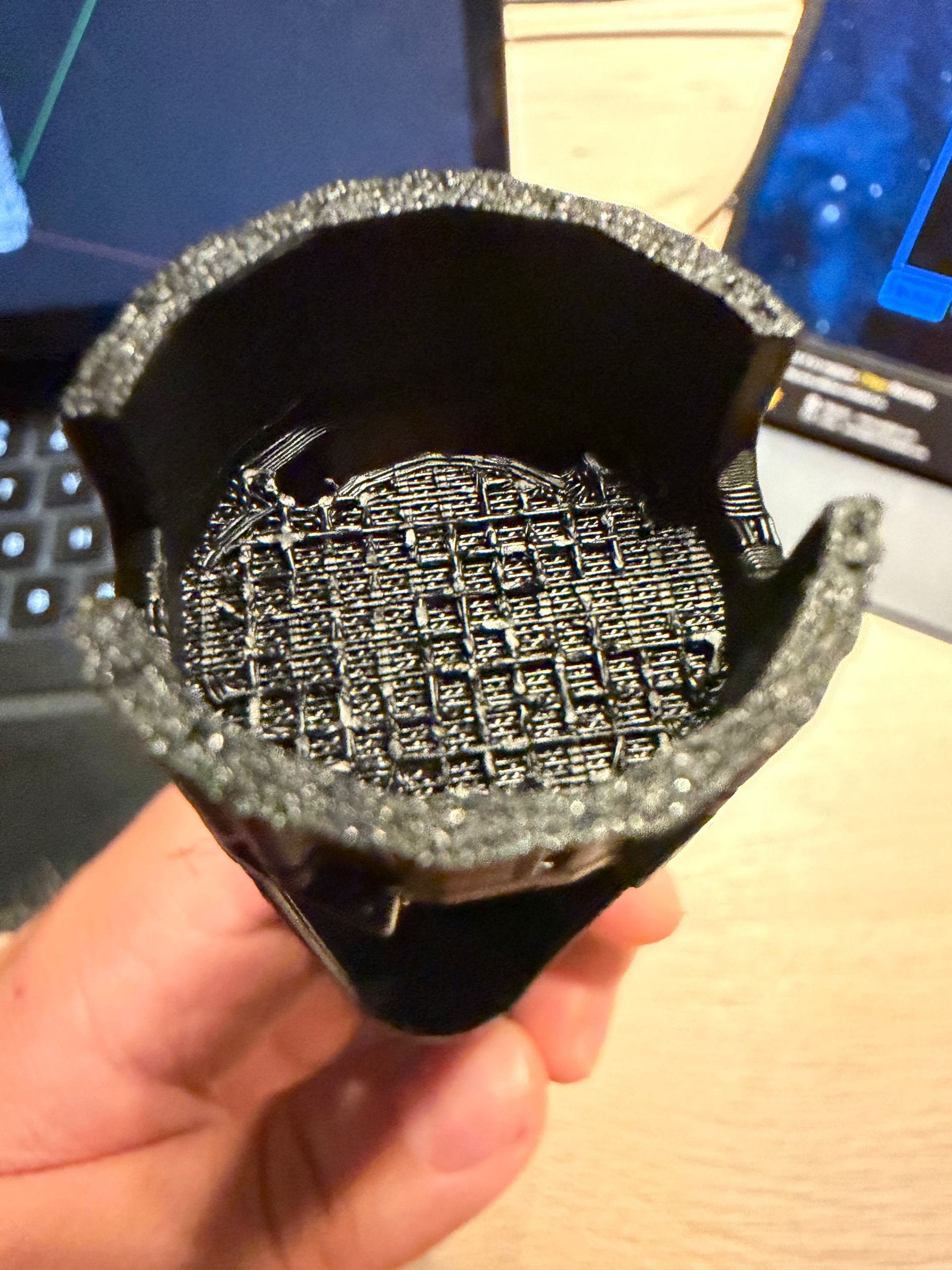
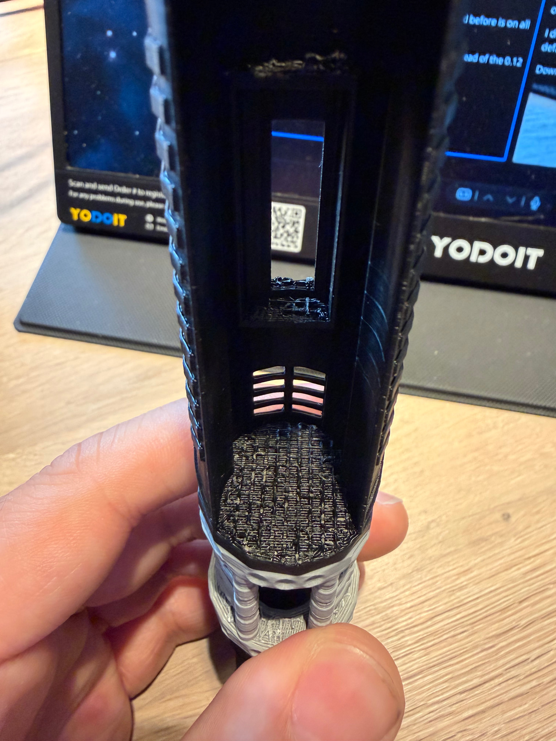
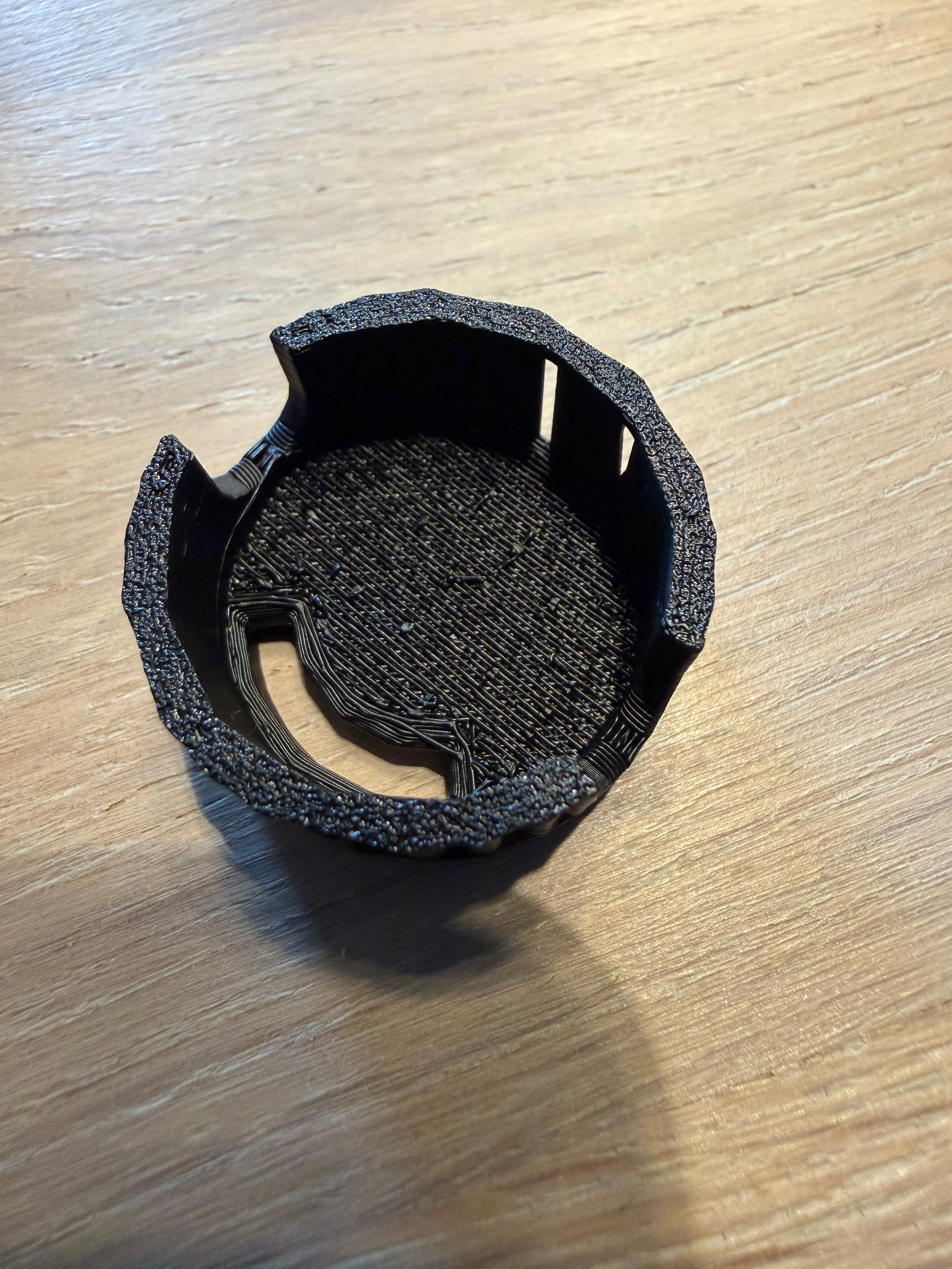
Also, I’m having some problems with flat areas which were supported on my print. The support interface layer really sticks to the model leaving me with an area such as this:
I’ve had these problems before, but I don’t really know how to fix it.
I’m using the ‘0.12mm High Quality’ profile on my Bambulab P1S with the addition of supports enabled ofcourse.
I’m using the official Bambu filaments, PLA only.
Most of these filaments are the Basic PLA.
Together with the AMS 1, which is pretty much filled to the brim with silica gel balls.
And I also store my filament in homemade nearly completely sealed containers with the same balls. The hydrometer tells me 10% moisture in those containers.
However, I recently printed something rather large using a higher layer height preset, and those came of like it wasn’t even stuck together at all.
I usually stick to the default presets which came with the software with slight adjustments to a few setting like brim type, supports and a few other basic settings. I rarely adjust any other settings because I don’t know what I’m doing
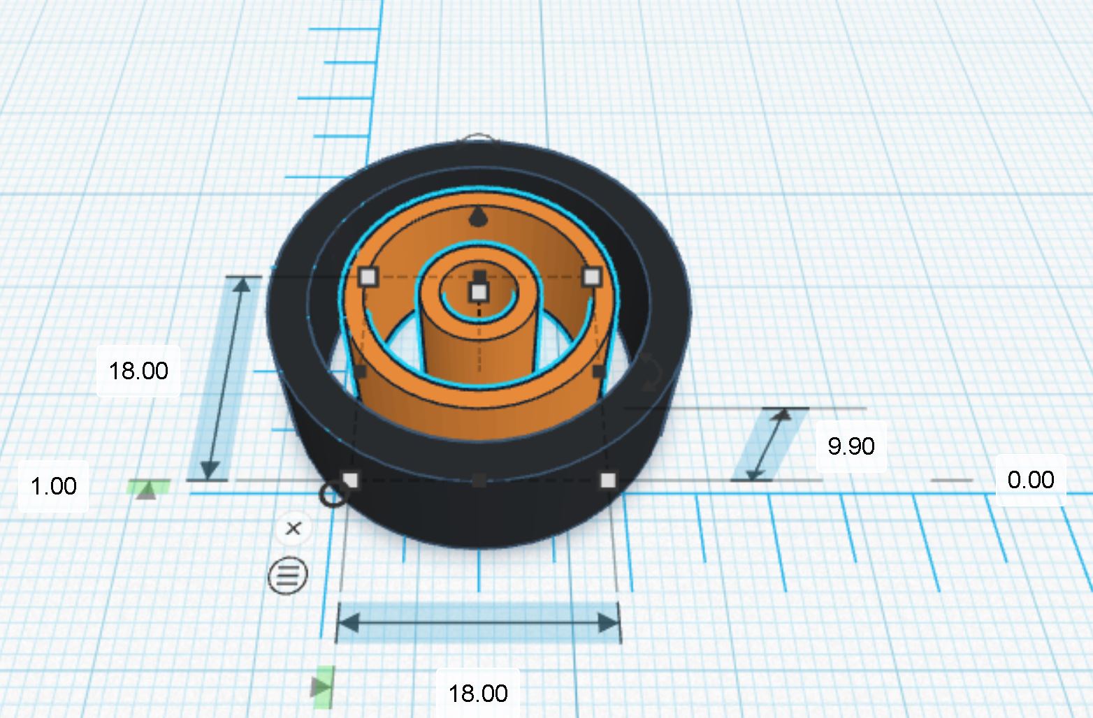
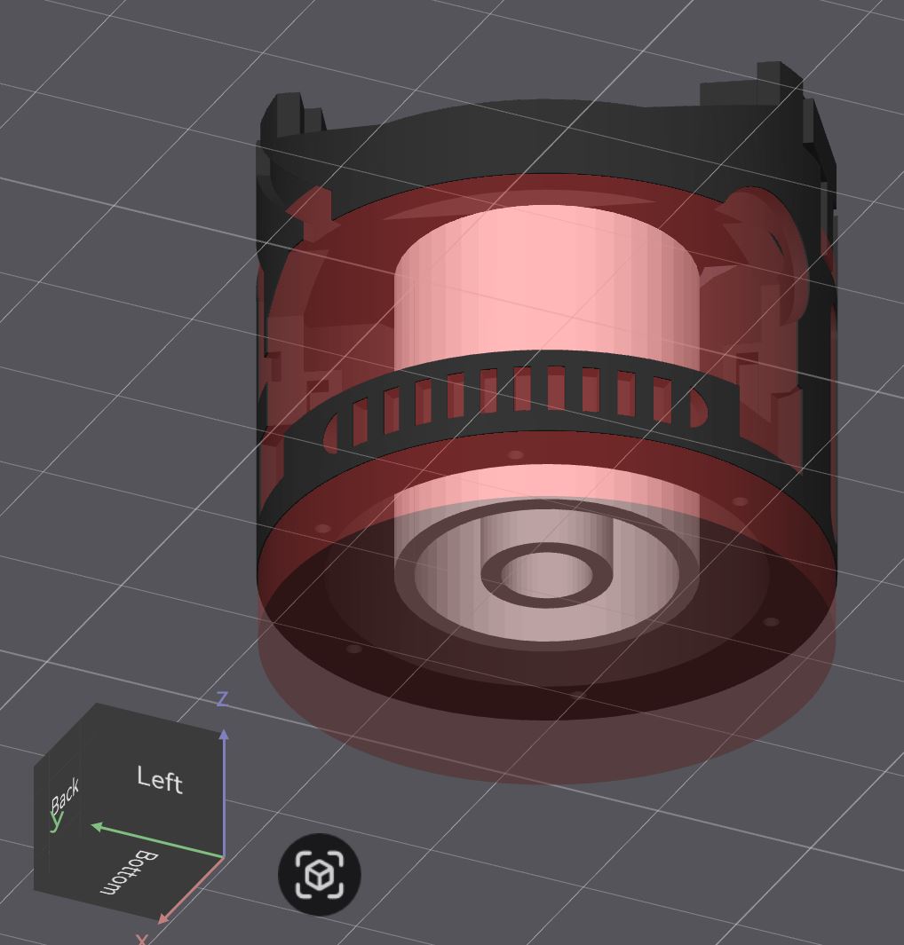
In this particular case, I would make a custom support part: a “double” thin cylindrical tube, 1.2 mm thick with an outer diameter two third of the inner diameter.
For example, if the inner diameter of your speaker “pod” is 27mm, make a tube of 18mm outer diameter, wall thickness 1.2mm (inner diameter = 18 - (1.2 x 2) = 15.6mm). Then make another tube with outer diameter of half of 15.6mm : 7.8mm.
Make the two tubes concentric and merge them, adjust the height so it is 0.1mm less than the height of the cavity.
Where the black is your chassis and the orange is your custom support.
In Bambustudio:
place your chassis in the center of the build plate
place your two tubes in the center of the build plate
merge the two together (you will get “1” piece separated by 0.1mm)
add a cylinder support blocker, in the center of the build plate, diameter at least as wide as the outer diameter of your chassis and as tall as the speaker cavity (I would add an extra millimeter)
It also seems like I loose a few details, so I just swapped my nozzle from 0.4 to 0.2.
But i’m not sure what layer hight I should choose for this. Maybe 0.10 High Quality?
Small amount of stringing will occur on unsupported horizontal parts.
You can use a windproof lighter (blue flame) to get rid of the strings, just apply the heat quickly (very quickly)!
The trick is to design parts without horizontal overhangs or minimum amount of horizontal overhangs. Use tree(auto) supports rather than “normal(auto)” supports. Become familiar with using tree(manual) supports and only use them where absolutely necessary. Start with a test print in white PLA because white will reveal all the flaws (they are easier to see).
Instead of horizontal unsupported area, you can use arches or slightly convex area.