I don’t know what is wrong in my head, the thickness of the wall of the cylinders should be the size of your nozzle, so 0.4 or 0.2 or a bit thicker.
With chassis parts, I have never seen detail improvements with the 0.2 nozzle. I don’t remember using anything smaller than 0.16 High Quality. But I have seen improvements with the “Variable Layer Height” tool from the toolbar. I crank it up to the max. No need to print a straight cylinder section at 0.1 all the way, that will just use a lot more time.
That’s actually a good point. I suppose I’ll just swap it back to 0.4.
I’m looking at my test print which is exported as a ‘low-quality’ model because I’m using the free version of Shapr3D. Essentially the cilinder is a 12 sided shape (like a hexagon, but 12 I don’t know the name of it)
I just applied for the free trial of 14 days so I can export with high quality.
I’ve used Tinkercad before, and while it was easy to work with, I could not get the same amount of details in the time I did it in Shapr3D using an iPad with the pencil.
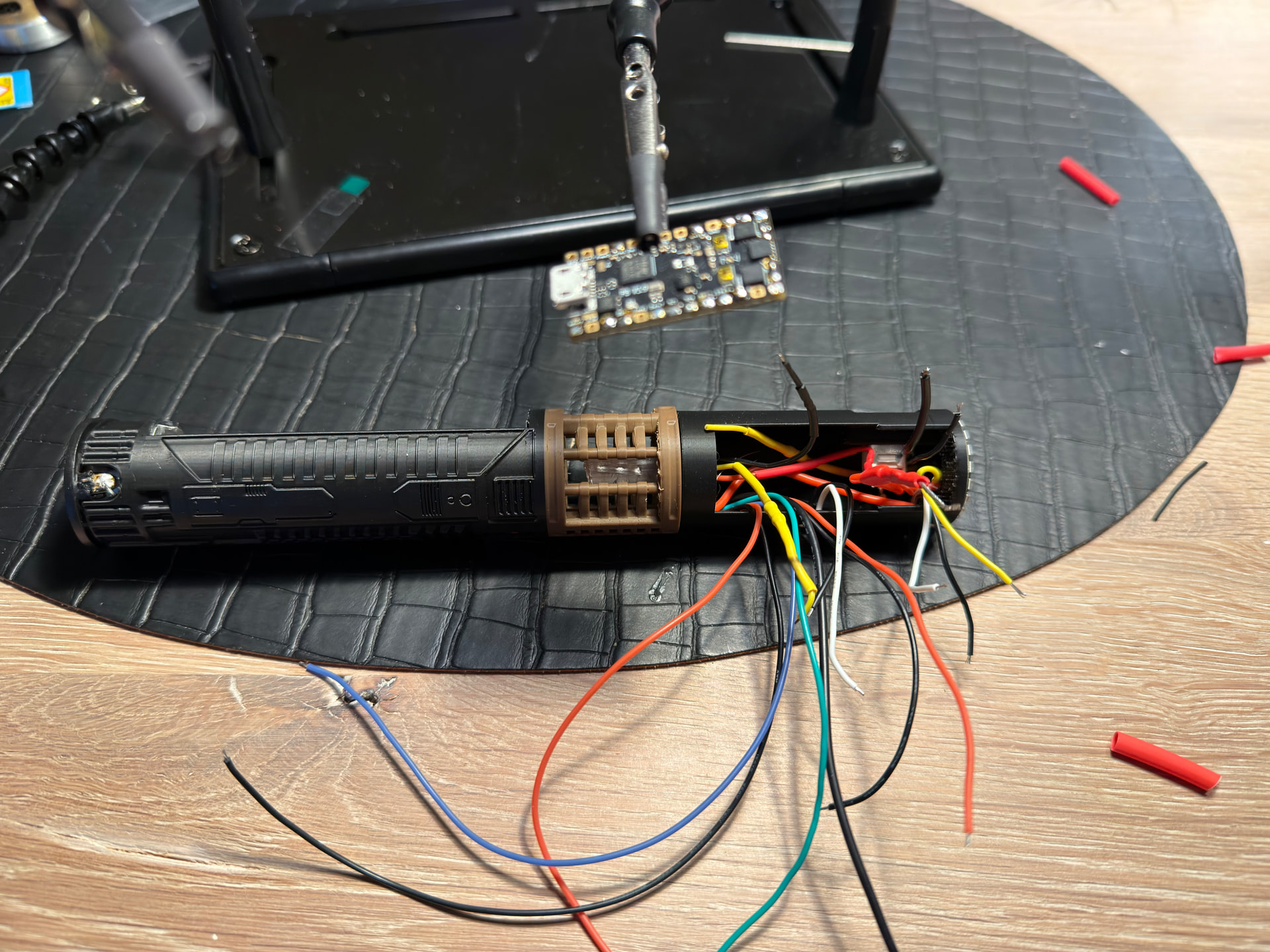
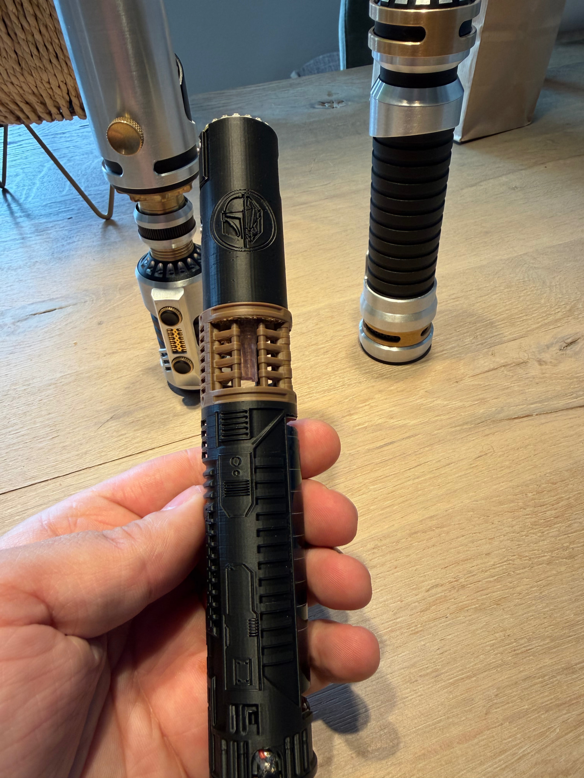
So today I finished up the last bits and pieces that were wrong with the test print and now have my final design printed.
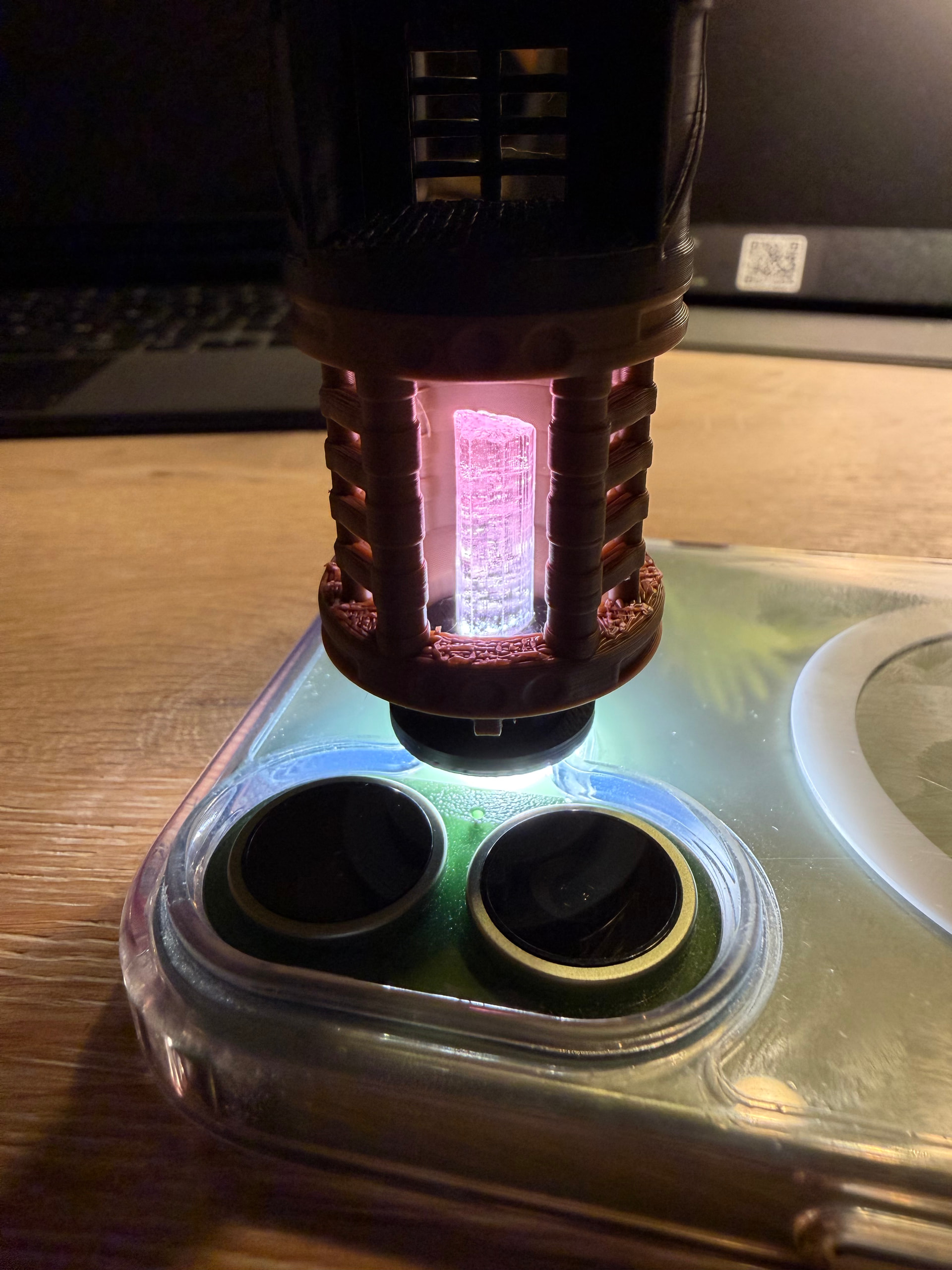
I also went to a mineral / gemstone store to buy my kyber crystal. In the end I bought a rose tourmaline crystal.
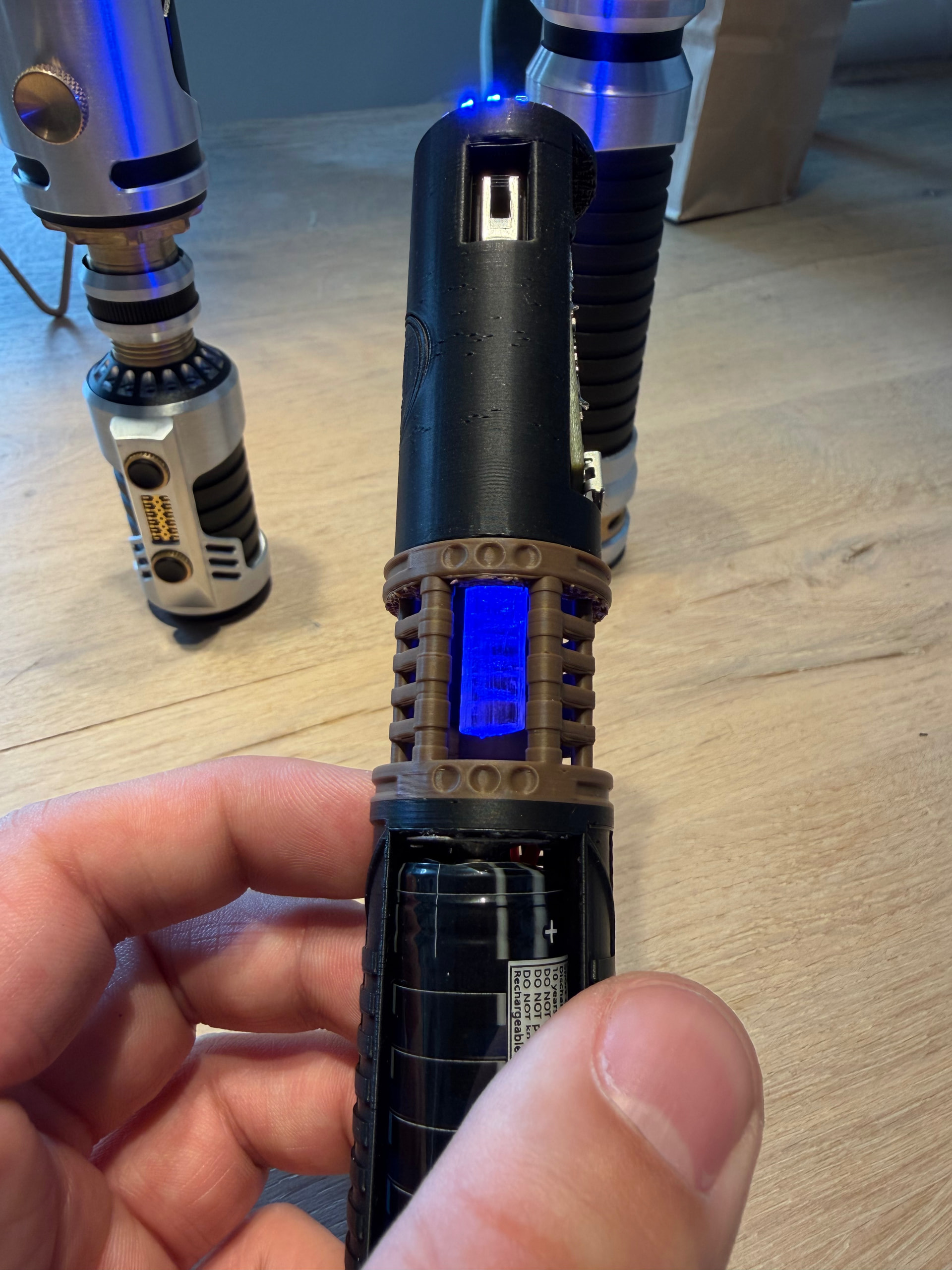
Small demo picture with a light on it. The housing I printed will also hold the 5050 Neopixel LED and is mounted at the top of the crystal chamber.
It was way to expensive but I thought is was very pretty and it fits my build. The stone is color graded from clear/white to pink. TBH, the image doesn’t do justice on reality.
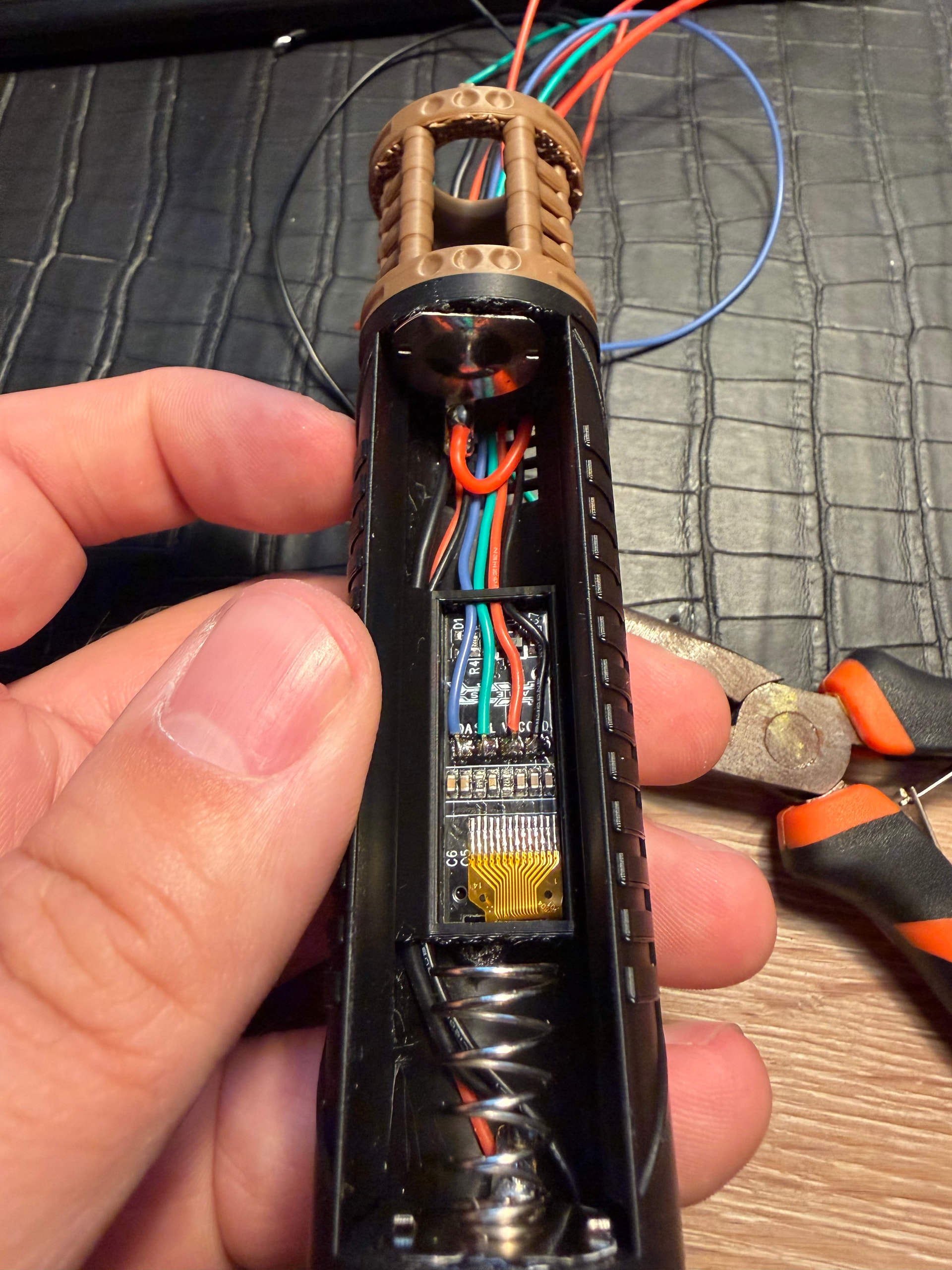
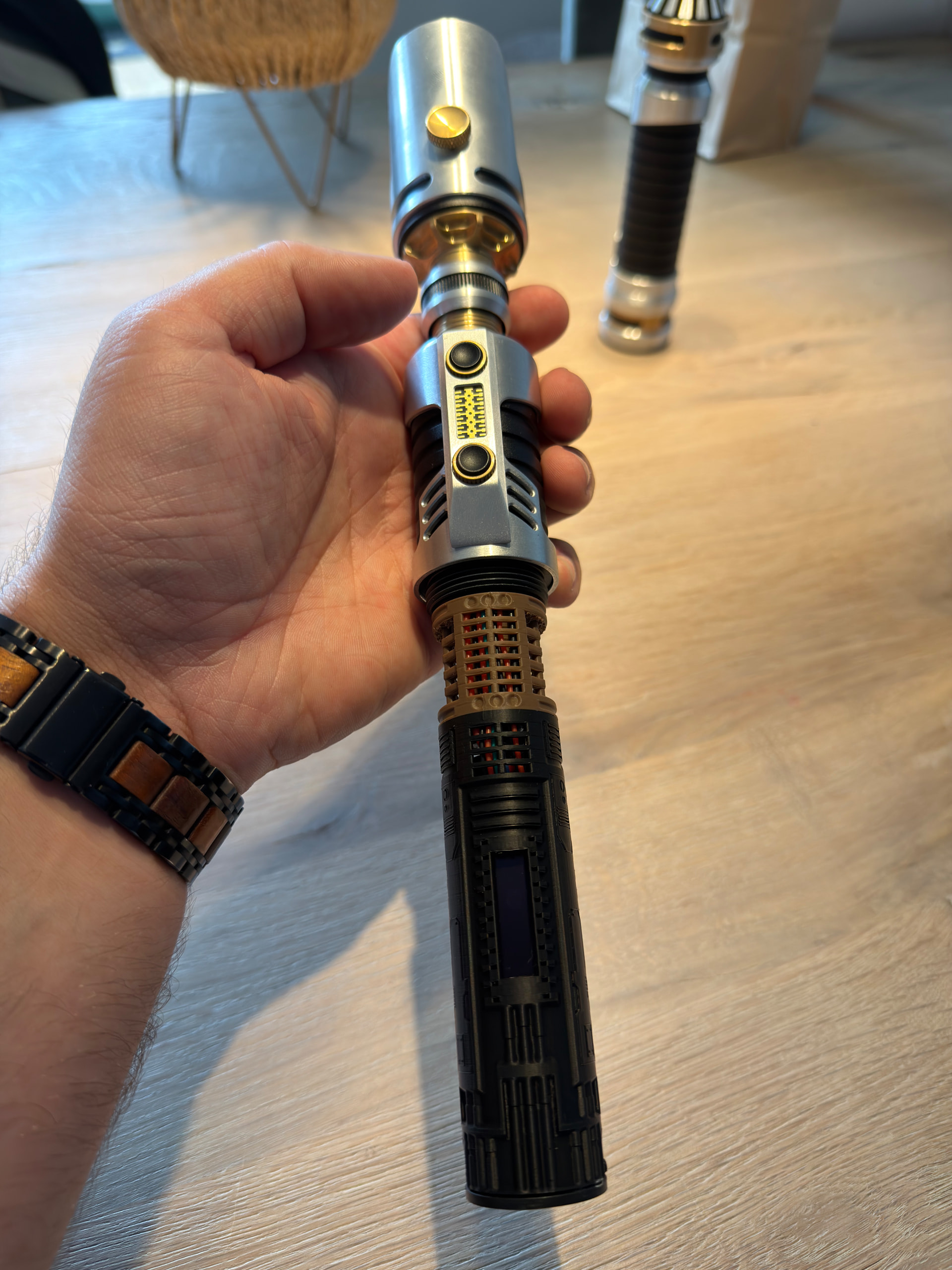
For this build I also bought the KR OLED display, but this is in my current print, a very tight fit. It pushes the band-cable (orange looking) a bit up if I were to press the display in the housing.
Is this a problem? Can I safely put some pressure on it?
What is usually the way to keep the display secured in the chassis?
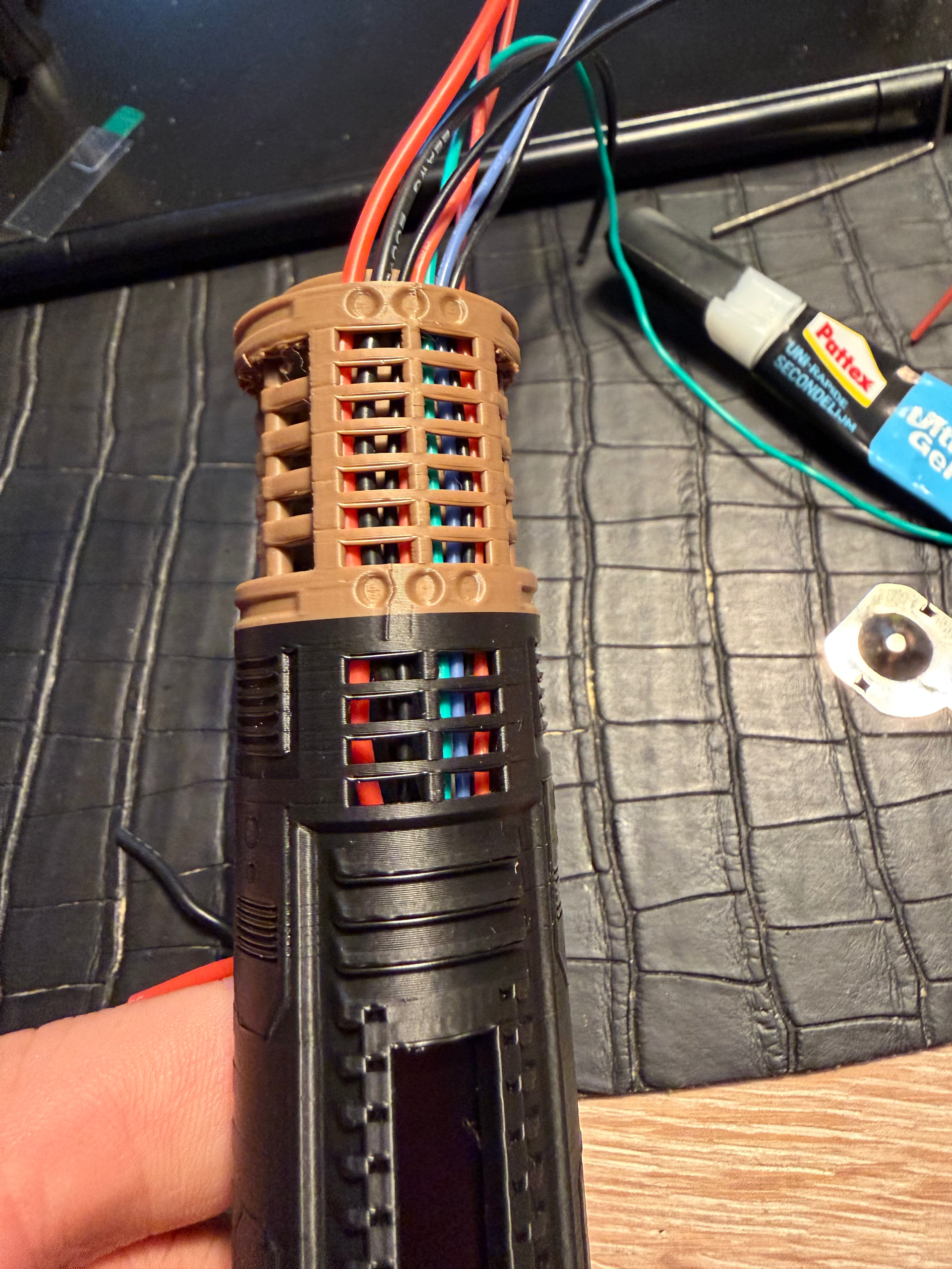
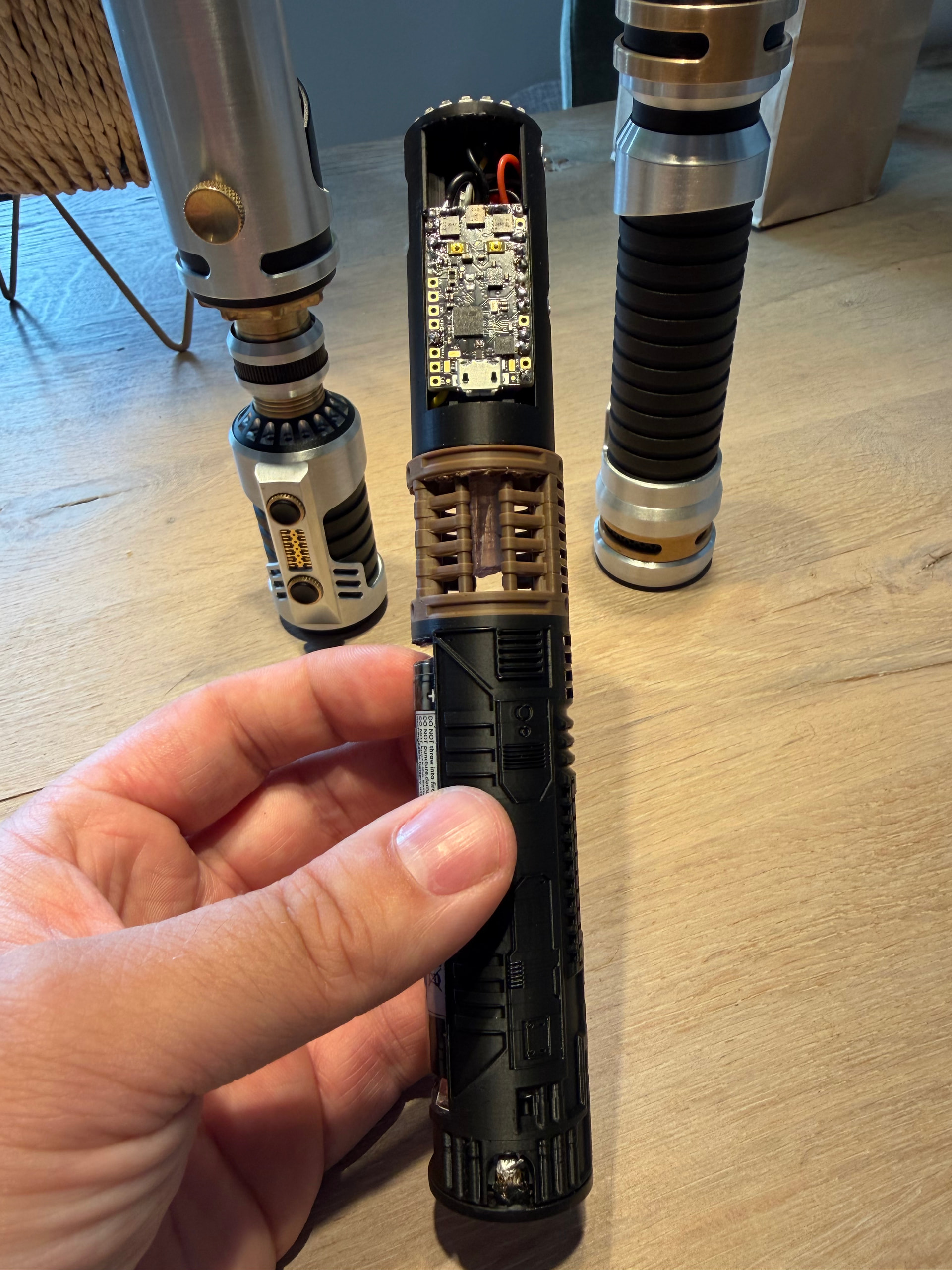
Some wires look beefy haha, but I shrunk some thingy I don’t know the name of over them to hold the resistor in place. The beefy red wire are all the positives (except for the OLED) combined so I can (I hope) more easily connect it to the board as one wire.
I’m especially happy with the battery compartment, how the wires are routed and the I actually love the visibility of the wires through the crystal chamber.
as for the PTFE, no I don’t?
then again, this is my first full chassis build from scratch (but the second I’ve done at all). The very first was a LGT conversion from Xeno to Proffie. There I did ordered new parts and printed a new chassis so I did not “destroy” my original. But this was basically the same as I already had
I really like the glow on the crystal! And I love the visible wires in the chassis.
As you can see, the original design had the proffieboard pushed up to the top, but because of the wires this was not possible anymore. A bit sad, but now I can just push up the board to access the usb-port or the SD card.