Hello everyone.
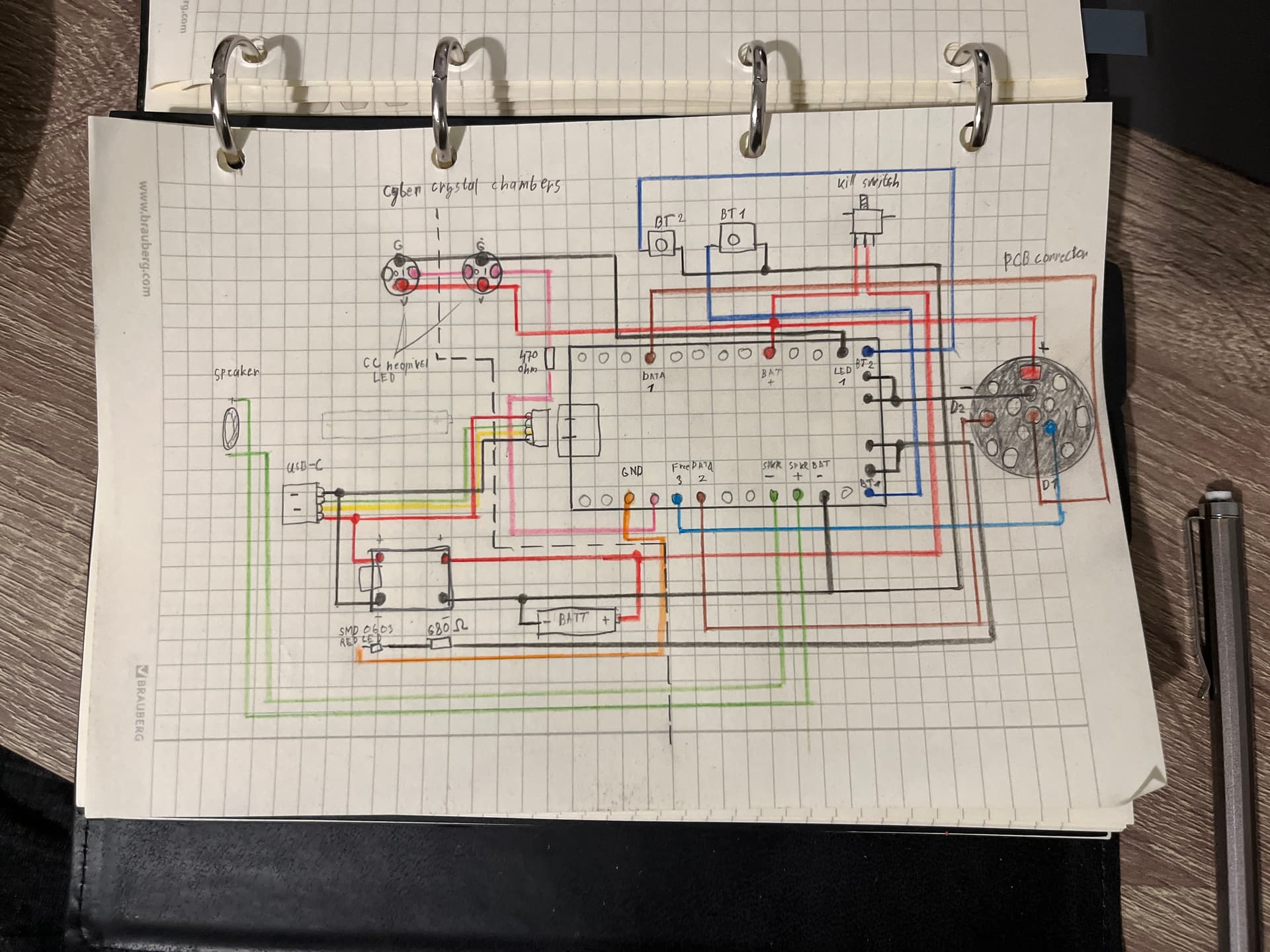
I need some help, I started a project to build my own lightsaber two months ago, I’ve read a lot of instructions and watched a lot of tutorials, but I still feel completely lost in the electrical design. In most manuals, the diagrams are different in one way or another (including in the configuration generator). Nevertheless, I was able to draw what is attached to my post(I know it looks terrible), and I just hope that it looks at least a little bit like the correct diagram. I hope someone can evaluate this and correct it, I don’t want to damage the electronics. I’m currently waiting for the components to be delivered, so I can’t test it out in practice. Here are the components that I’m going to use:
USB type C port and lithium ion battery charging kit
keep power 18650 3.7V 3500 MAH 15A high drain PCB protected removable lithium ion battery
Keystone Battery holder 18650
SMD 0603 red LED - charge indicator
This is my first time doing anything with electronics, and it’s quite complicated for me. I’m sorry if my writing is strange or unclear, as English is not my native language.
I would be grateful for any help.
However I do see some issues with it. For one, you have the led pads hooked to an led, then to gnd. The led pads are the negative feed to the leds, so that should be positive power of some kind.
Why do you have a usb c connector if you have a removable battery? Usually it is to charge the battery on board. You could consider removing that to simplify things since it is your first time?
Also, your post was clear and understandable, so good job there!
Since you’re using an external charger, the Proffieboard won’t really know when you’re charging or not. The “charge indicator” will need to be wired to the battery charging board, not the Proffieboard.
Welcome to the Crucible. There is one more thing that you may want to consider.
You very nice diagram has your kill switch between the battery and everything else, it is not wrong as long as your main blade is “standard” 144 LED or less.
However if you plan use a main blade with a lot more LED (288, 400+, …), you will want to have the kill switch between the Proffieboard and everything else (battery, leds, charge port, …). Like that not all the Amps needs to go through the kill switch, but the kill switch will cut the power to your Proffieboard which will cut the power to everything else.
You can find examples of wiring the kill switch here:
(on pages 8, 10 & 12)
(English is also not my first language)
Edit: Or at the very least, you’d probably want the “+” of the PCB connector connected between the battery and kill switch, then everything else (crystal chamber LEDs, other small led, Proffieboard, …) after the kill switch, because your main blade could potentially draw too much current for the kill switch. But if no power to Proffieboard, then no data is send and all the LED’s should be off.
Thank you, You’re right about the LED connection, it’s indeed connected to two negatives, so I guess I should connect the second pin not to GND but to BATT+?
Yes, I want to install a charging port because it’s more convenient to use, as I see it, and it doesn’t significantly complicate the overall design. I use a battery holder because it already has the necessary attachments, so I don’t have to create them myself. Additionally, I want to be able to quickly replace the battery in case of malfunction.
You’re probably right, and it can be done more easily.
Hi
Yes, thank you for that comment. I wasn’t very attentive when I drew it. Of course, it’s better to place the killer switch on the circuit before all the electronics. I read the manual you attached, and it’s really helpful.
Hi, that’s intresting
Hmm, the external charger doesn’t transmit any data to the board? or is the board unable to process this data to display the charge indicator?
Also correct.
You could add a wire that tells the board if it is charging or not, but you would need to add a bit of code for it as well. (Or use the new ReadPin style.)
Hard to say since I don’t know what charge controller you’re using and what it can do. Most likely, you would need to hook up the wire to the charging LED on the charging board though.
So is this a solution at the program code level? Do I need to change the LED connection for this? (Proffieboard LED > resistor > SMD LED > Proffieboard BATT +)
Well, you may want to consider wiring the charging led directly to the charging board, as that would be much simpler and also work while the Proffieboard is off.
Wiring the charging signal through the proffieboard and using ReadPin will work with the LED setup you have, and it means you can do things like adjust the brightness, blink, pulse or whatever, with the LED.
You might want to look at blade plug charging. The plug charger is very easy to make using a TP4056 board, and it means all the charge handling is external to the hilt, thus simplifying your saber install hugely. All you need is a few lines of code in the config to make it work.
This clip shows the idea of how it works:
When I get home from work today I’ll post up the bits of code you need and details of how to make the charger.
Then you need to add a charging preset. You can specify any font on the SD card as it won’t actually be using it:
//  FOR BLADE PLUG CHARGING.
   { "Graflex", "tracks/mars.wav",
//  Main Blade:
ChargingStylePtr<BlackPower>(),
"charging"},
If you have any accents, just set them to: StylePtr<Black>(),
This idea is the BlackPower blade style keeps the blade FETS powered, but the style tells them not to light anything up. This allows current to pass from the charge plug through to the battery.
Then in the charge plug you simply wire the TP4056 board’s Batt+ and Batt- terminals to the corresponding blade disc terminals (outer ring and mid ring respectively) and then fit it into an offcut of blade tube.
If you look on the thread below, there are some downloadable STL files - kindly supplied by @baldusi, so you can 3D print the plug charger components yourself. The thread shows additional pixel LEDs built into the plug charger which you can add if you want to get fancy, but you don’t have to add them as the TP4056 has its own LEDs built in to handle the blue/red status indicator automatically.