My config upload stopped at 95% and now my board don’t work anymore. Only showing a green LED when plugged in via usb c. Now I don’t know what to do because I can’t connect the board to my Mac and at the same time I can’t start the bootloader because my boot button is probably useless. Also English is not my native language what makes it even more difficult for me to sort my problem out :’)
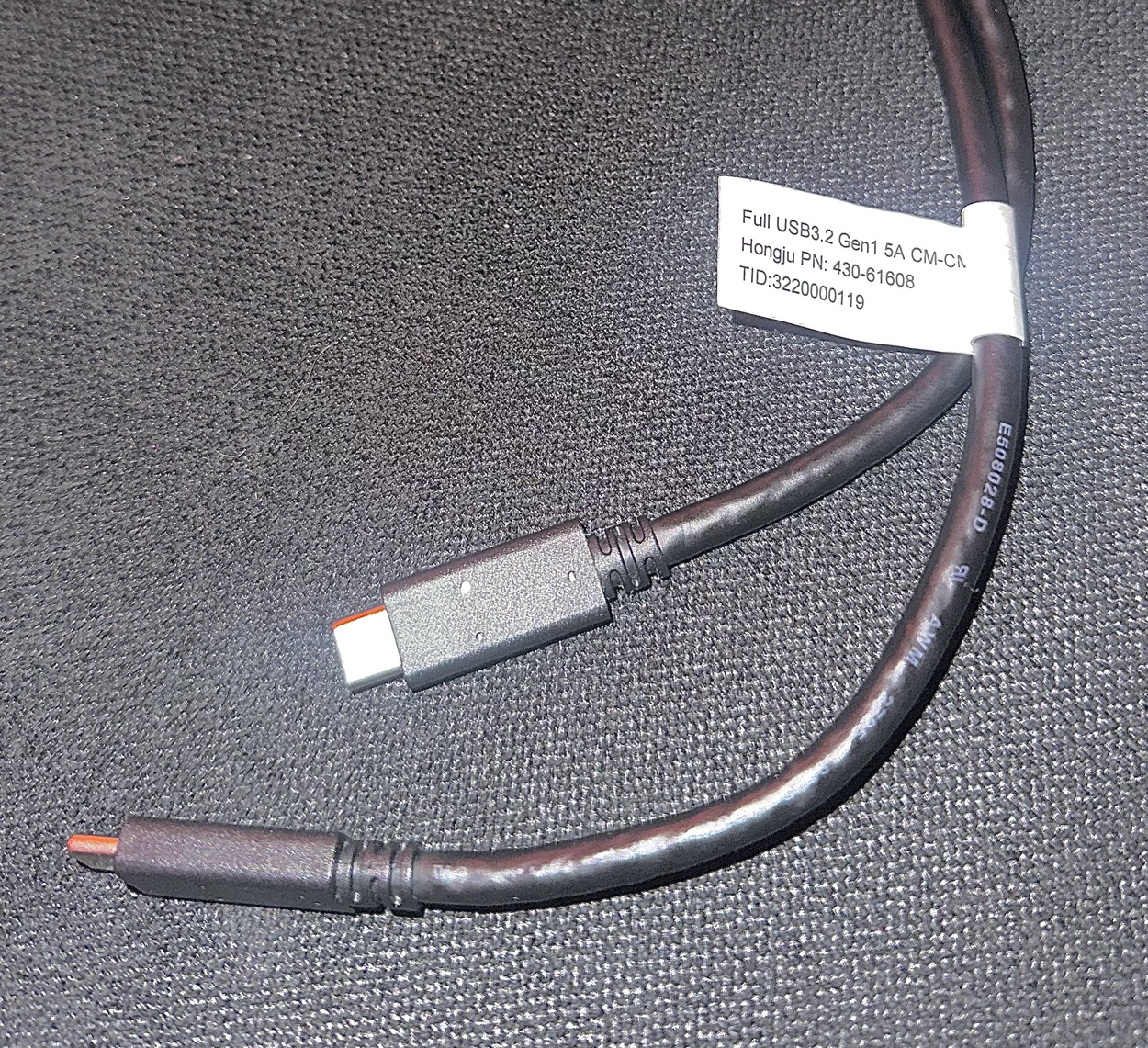
Do you know why it stopped? Maybe your USB cable is not good?
Why can’t you connect?
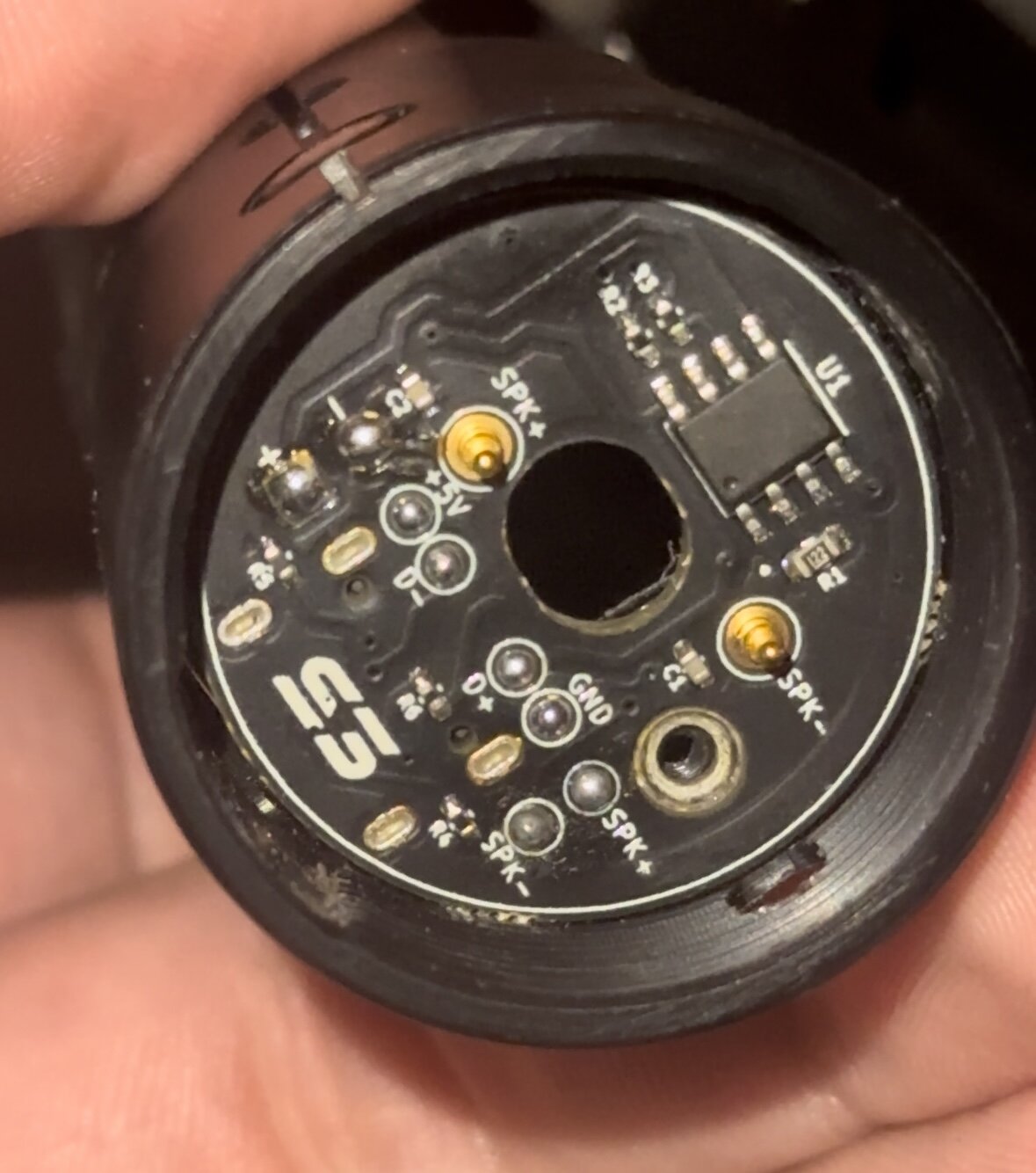
As far as the BOOT button, you do need that. It looks like the pad is still intact. If you can solder a small wire to each pad where the button was, you could just short them together, plug in USB, then disconnect the wires. That should put you in bootloader , and you can just hit Upload in Arduino with a known-good config file (like the default_proffieboard_config.h)
I have no skills when it comes to electronics. Soldering will also be difficult because I don’t even have the necessary accessories… Can I simply short-circuit the BOOT pad to activate it using a screwdriver as an example?
Messing up the config file will cause an error, it won’t stop the upload midway through.
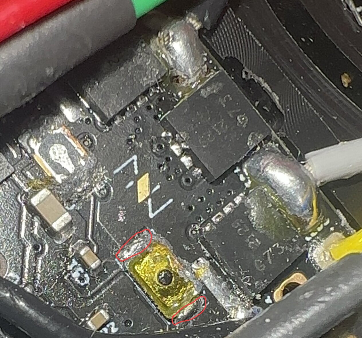
You’ve got a blown FET there, maybe you shorted something out and that caused the protection PCB to trip, interrupting the upload?
Is that cable a USBC-USBC? Does that mean you have an expansion board and aren’t connecting to the onboard USB connector?
Yes, if you can successfully bridge/short those pads that way while you apply power it should do the same thing, but I’d expect to maybe do a couple times since it’d be fiddly.
No, don’t bridge. He’s saying solder a wire to each pad, then short the ends of the wire together. If you’re careful, I think you can also just short the pads manually with something if you’re steady enough.
It’s hard to tell from these pictures, but there is a pad under each of the short ends of the button, and those are the ones that needs to be shorted. It’s possible that you can do the way you shown in the image, but I’m not sure. It could be that it would be easier to just remove the remains of the button with a solder iron, and then work on shorting the remaining pads with a paperclip or something.
Okay with other words I probably cant make any progress because I’m a noob in the electrical craft sector. I was hoping that I can sort this out with some tools everyone has at home
Can’t I just mount the reset button on top of the other one without much effort because this one is working? (That was my first taught and show how much I understand about this technology and how it works)
It’s very difficult for me to understand how exactly I should do this because I have no knowledge of electronics and I only spoke English at school… And it’s all so delicate that I really have to implement everything precisely because otherwise I damage even more I think
`
I’m also unsure now what the pads are. Maybe you could edit my picture to show me what I need to short together I would appreciate that very much
The parts inside the button (highlighted previously in this thread) may be connected to these pads, but I’m not entirely sure what connects to what, so it’s probably easier to short the pads directly.
I would probably try to make something out of two pins (sewing pins) and a bit of wire to do the shorting with as much precision as possible.
Tried to short it now for about 30 minutes but don’t get any device input. I think I give up on that. I’m already 3 days into somehow get it work again
It would probably be best to just buy a new board. Even when I get it into bootloader I dont know if it works again. Could be more that causing the board to not work right? But a new board means whole new Power Core from s3… 300$
Also don’t know what’s best…killswitch on or off, with sd or without? BOOT+RESET while plugged? Just BOOT and then plugging? How do i know if it has worked the fastest? (At the moment I wait for it to show on desktop)
Assuming you’re using windows, the way to know if it works is to check if “STM32 BOOTLOADER” shows up in “printers and devices”.
The “fastest” way would probably be to plug it into USB (doesn’t matter if kill switch is on or off, or if the SD is connected or not) then short boot, and try to click reset while boot is shorted. If it works, STM32 BOOTLOADER should show up in “devices and printers” a second later.
If that turns out to be difficult, you could try disconnecting USB and turn the kill switch off. Then short BOOT and flip the kill switch. Then connect USB and check for “STM32 BOOTLOADER” in printers and devices. Note that if it doesn’t work, you have to disconnect USB and turn the kill switch off again, which is why this method might be a lot slower. (But it might also be a lot less fiddly, since pressing reset while shorting BOOT might be difficult.)
Since this is a V2 board, which doesn’t have it’s own status LED, I have no idea what this means.
Sorry forgot to say again that I’m using MacOS with M1 chip. (Mentioned it only in the topic)
They say: “To show the charging status, we have integrated a small status LED into the chassis that resides behind a piece of acrylic that allows the LED’s illumination to be properly diffused and be clearly visible”