Will try this. So I’m assuming the charging status LED doesn’t matter? I just don’t understand that with different setups it changes that much ![]()
Probably not, but I don’t actually know.
I would assume they have a battery charging circuit in there. You don’t specify if USB is connected during those states above, as that could explain why the green LED is lit, as it’s getting power from the USB cable.
Do you have a USB-C port on the saber? Or have you been using the onboard microUSB port? (on the Proffieboard itself).
I would suggest using the normal connection to get this up and running.
You’d need a USB-C to MicroUSB adapter thing, something like this:
https://a.co/d/3tQ43t4
or just an actual male USB-C to male microUSB cable.
Also, I think the pad got ripped off based on this:
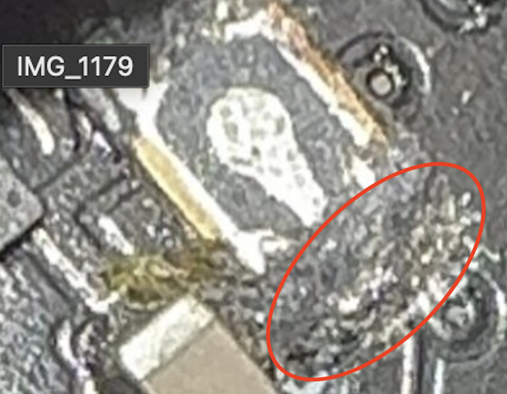
That should be a shiny bar where there’s nothing. The small trace heading south from the area might be the only point you’d get contact.
You could scrape away some of the masking covering that line with a pin to expose some more copper. This is all very small work by the way. I don’t suggest coffee.
What about just using RebootDFU and forcing the upload so you bypass the need for the buttons?
Don’t know how this works.
Always connected.
Yes they added a USB C port for charging and data transfer. The USB C port is connected via Micro USB to the board.
So I need to scrap a little bit away in the area you marked?( Don’t know if I get you right)
That only works when the board is successfully booted into ProffieOS.
A borked board isn’t running anything.
If USB is connected and powered on then trying to toggle the BOOT button via jumping won’t do anything.
The BOOT button must be held during power on to enter bootloader mode.
Take a look at this link (open it in a new window so you can see this images).
This repair thread post has a similar situation where the contact pad ripped off with the component. Look how I scraped away some masking along the thin line of copper (called a trace) that used to connect to the pad. This made a surface that the solder could stick to instead of the missing pad.
I don’t think the button has been completely torn off, because the stuff we see in the picture is an internal button bit. It’s just the top part of the button that has gone missing. I’m not sure why the pads are hard to see in the picture, it looks like there might be some gunk or melted plastic on there maybe?
1 Like
True, if the button contacts are there that would mean the plastic bed is too, so it’s just ugly dirty plasic/solder. Could scrape away some of the black over the pad and get to shiny solder, that could work. The right answer is to just float off what’s left of the button of course.