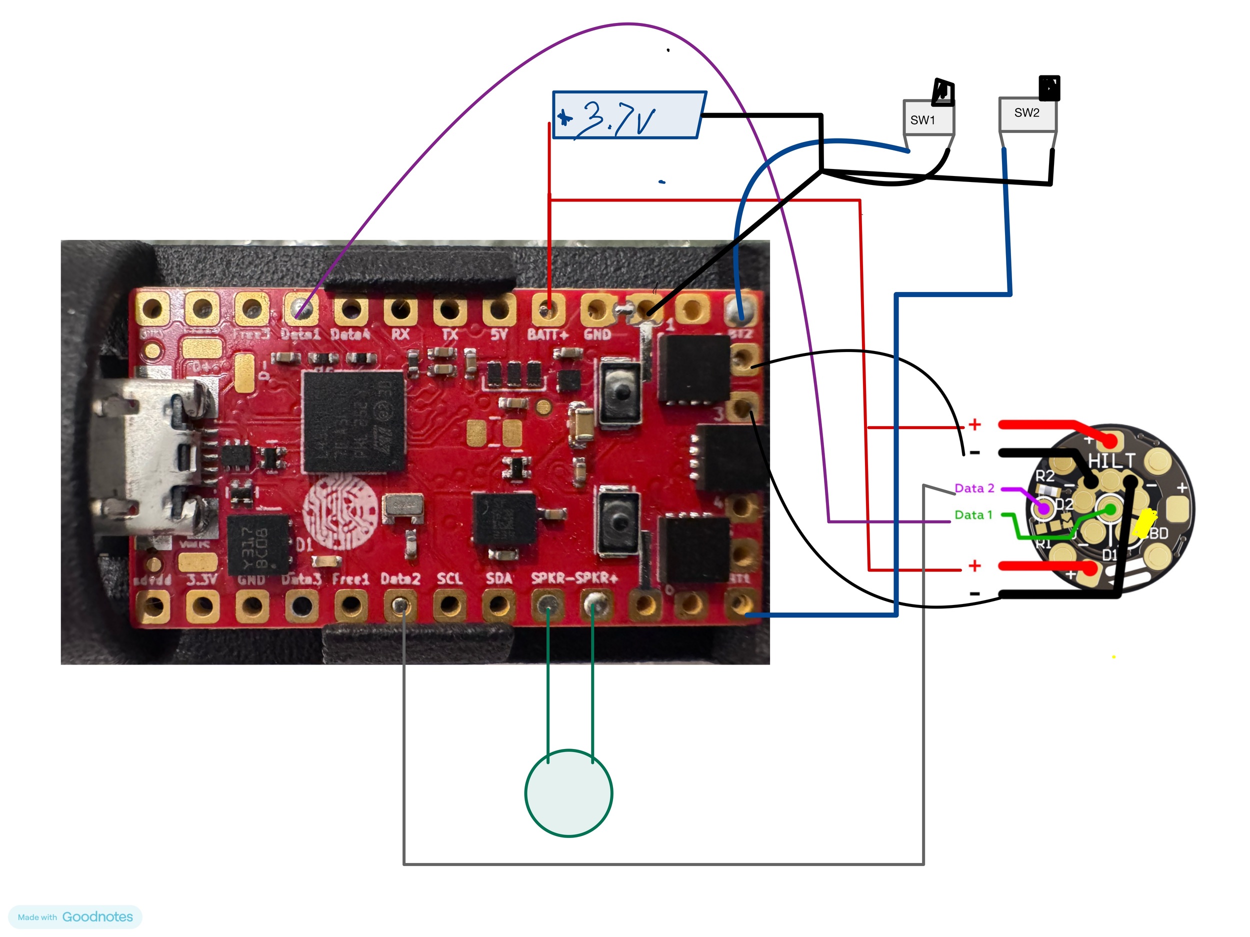
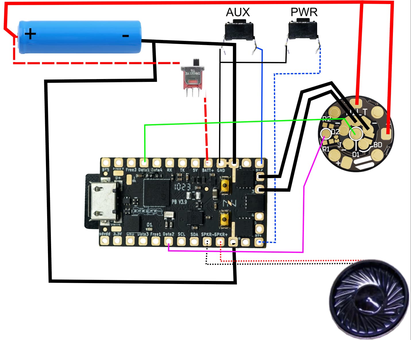
hi all. so I have things wired up and I can see the PCB lights up fine but my blade does nothing. I took it apart to confirm I have the pads soldered . my config look like this. I was playing around and now I just get an error when trying to compile it.
#ifdef CONFIG_TOP
#include "proffieboard_v3_config.h"
#define NUM_BLADES 3
#define NUM_BUTTONS 2
#define VOLUME 1000
const unsigned int maxLedsPerStrip = 147;
#define CLASH_THRESHOLD_G 1.0
#define ENABLE_AUDIO
#define ENABLE_MOTION
#define ENABLE_WS2811
#define ENABLE_SD
#define SHARED_POWER_PINS
#endif

#ifdef CONFIG_PRESETS
Preset presets[] = {
   { "TeensySF", "tracks/venus.wav",
    StyleNormalPtr<CYAN, WHITE, 300, 800>(),
    StyleNormalPtr<CYAN, WHITE, 300, 800>(),
    StyleNormalPtr<CYAN, WHITE, 300, 800>(), "cyan"},
   { "SmthJedi", "tracks/mars.wav",
    StylePtr<InOutSparkTip<EASYBLADE(BLUE, WHITE), 300, 800> >(),
    StylePtr<InOutSparkTip<EASYBLADE(BLUE, WHITE), 300, 800> >(),
    StylePtr<InOutSparkTip<EASYBLADE(BLUE, WHITE), 300, 800> >(), "blue"},
   { "SmthGrey", "tracks/mercury.wav",
    StyleFirePtr<RED, YELLOW, 0>(),
    StyleFirePtr<RED, YELLOW, 1>(),
    StyleFirePtr<RED, YELLOW, 2>(), "fire"},
   { "SmthFuzz", "tracks/uranus.wav",
    StyleNormalPtr<RED, WHITE, 300, 800>(),
    StyleNormalPtr<RED, WHITE, 300, 800>(),
    StyleNormalPtr<RED, WHITE, 300, 800>(), "red"},
   { "RgueCmdr", "tracks/venus.wav",
    StyleFirePtr<BLUE, CYAN, 0>(),
    StyleFirePtr<BLUE, CYAN, 1>(),
    StyleFirePtr<BLUE, CYAN, 2>(), "blue fire"},
   { "SmthGrey", "tracks/venus.wav",
    StylePtr<InOutSparkTip<EASYBLADE(MAGENTA, WHITE), 300, 800> >(),
    StylePtr<InOutSparkTip<EASYBLADE(MAGENTA, WHITE), 300, 800> >(),
    StylePtr<InOutSparkTip<EASYBLADE(MAGENTA, WHITE), 300, 800> >(), "magenta"},
   { "SmthFuzz", "tracks/mars.wav",
    StyleNormalPtr<Gradient<RED, BLUE>, Gradient<CYAN, YELLOW>, 300, 800>(),
    StyleNormalPtr<Gradient<RED, BLUE>, Gradient<CYAN, YELLOW>, 300, 800>(),
    StyleNormalPtr<Gradient<RED, BLUE>, Gradient<CYAN, YELLOW>, 300, 800>(), "gradient"},
   { "RgueCmdr", "tracks/mercury.wav",
    StyleRainbowPtr<300, 800>(),
    StyleRainbowPtr<300, 800>(),
    StyleRainbowPtr<300, 800>(), "rainbow"},
   { "TthCrstl", "tracks/uranus.wav",
    StyleStrobePtr<WHITE, Rainbow, 15, 300, 800>(),
    StyleStrobePtr<WHITE, Rainbow, 15, 300, 800>(),
    StyleStrobePtr<WHITE, Rainbow, 15, 300, 800>(), "strobe"},
   { "TeensySF", "tracks/venus.wav",
    &style_pov,
    StyleNormalPtr<BLACK, BLACK, 300, 800>(),
    StyleNormalPtr<BLACK, BLACK, 300, 800>(), "POV"},
   { "SmthJedi", "tracks/mars.wav",
    &style_charging,
    StyleNormalPtr<BLACK, BLACK, 300, 800>(),
    StyleNormalPtr<BLACK, BLACK, 300, 800>(), "Battery\nLevel"}
};
BladeConfig blades[] = {
 { 0, WS281XBladePtr<144, bladePin, Color8::GRB, PowerPINS<bladePowerPin2, bladePowerPin3> >(),
    WS281XBladePtr<16, blade2Pin, Color8::GRB, PowerPINS<bladePowerPin2, bladePowerPin3> >(),
   CONFIGARRAY(presets) },
};
#endif

#ifdef CONFIG_BUTTONS
Button PowerButton(BUTTON_POWER, powerButtonPin, "pow");
Button AuxButton(BUTTON_AUX, auxPin, "aux");
#endif