
Note the battery icon, which is on a separate, mostly transparent layer. It also uses a variable to decide how many green bars to show, based on conditions in the battery file itself…
Note the battery icon, which is on a separate, mostly transparent layer. It also uses a variable to decide how many green bars to show, based on conditions in the battery file itself…
Using this overlaid on the board itself could create some cool effects! Also, could somethign like this fit inside the control box of a Luke Hero?
You can also put an entire SW movie on loop in the background. ![]()
Maybe:
More information here:
That is looking beautiful!
I was wondering how animations would look, this answers that.
It seems you’re using the flat cable it comes with, do you know how many pins we’ll end up using?
Well, let me see… we need: clock, data out, command and light, so four. (Plus power obviously.)
Some displays also need a chip select pin, but on this one tying it to GND works well.
Currently the code also uses up one pin for data in, but that is not actually used, and I will fix that before ProffieOS 8 is released.
Because it needs a fair number of pins and memory, color screen support is only planned for V3 boards right now.
Only four pins!
That’s great!
Since I have the same screen and V3 boards, I’m happy to see I’m all set.
I just need to finish my build, if only it decided to not be a pain in the butt to design so much ![]()
wow wow wow … wow.
.
.
This is a completely new level.
It really is.
Even this tiny display requires a bitrate of ~6Mbit/s to show animations, or ~8 “streams”.
It’s 160x80 pixels, which is kind of like driving 88 144-pixel blades at the same time.
At least it doesn’t need the embedded nuclear reactor it would require to power all those neipixels!
Inventing the thing I want to learn next! Oh my!
My thought is you could have a really cool reveal of the inner workings of a part of the hilt. Hell, you could have a digital crystal chamber!
when you get to 88 pixel blades, you’re going to see some serious S
Ok, all the changes are checked in…
I need to make a new experimental release of the arduino-proffieboard plugin, it’s not strictly required, as it will work with the 3.7 version, but with some additional changes we can have support for 40Mhz SPI and no MISO pin.
Unfortunately, it doesn’t perform as well as I would have hoped with largish (320x240) displays. The frame rate is limited to 5-10 fps right now, depending on the complexity of the content.
Smaller displays, like 160x80 or 160x128 work quite well though, although I haven’t done much testing with complicated setups and lots of blades yet.
Hopefully I can make the experimental arduino-proffieboard release tomorrow, and then I can write up some guides for how to wire things up and create animations. Then the fun part starts. (debugging)
Just ordered 2 160x80 from DigiKey. ready to play!
Looking forward to how-to on the images.
I saw this last week on your YT channel.
Very cool and I may have to consider this option for the next coaxium (saber/Sabacc) case build.
I made a readme file for the pqoi tools:
It’s a little more bare-bones than the final documentation, but covers the basics.
Oh, and I’m attaching some sample 160x80 PQF files to this post.
m160x80.pqf (2.3 MB)
batt160x80.pqf (5.5 KB)
Not making any guarantees about these files, but I have been using them for testing quite a bit.
EDIT: This is about half the information needed, I also need to document how to SCR files, hook up the displays and what to put in the config file…
Ok, I have updated the experimental proffieboard plugin to 4.0, which includes these changes:
Note that you need Arduino 2.x to install this plugin. However, once installed, you can use Arduino 1.x if you prefer.
It may be theoretically possible to use the existing arduino-proffieboard plugin with color displays, but I ran into some pretty awful compiler bugs, which made lots of things just not work, so I would not recommend trying that.
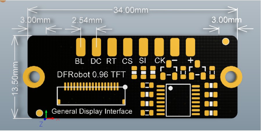
Here’s how to wire one of these color displays:
| Display Pad | PBV3 | function |
|---|---|---|
| BL | Free2 | Backlight control |
| DC | Free3 | Command Select |
| RT | no connect | Reset |
| CS | GND | Chip Select |
| SI | Data3 | Data |
| CK | Free1 | Clock |
| + | SD_VDD | power |
| - | GND | power |
If you want to use an Adafruit EYESPI connector it’s the same thing, but the names are different:
| EYESPI | PBV3 | function |
|---|---|---|
| TCS | GND | Chip Select |
| RST | no connect | Reset |
| DC | Free3 | Command Select |
| MISO | no connect | |
| MOSI | Data3 | Data |
| SCK | Free1 | Clock |
| Gnd | GND | power |
| Lite | Free2 | Backlight control |
| Vin | SD_VDD | power |
If you’re planning to use a ST7789-based display, then you need to connect CS/TCS to some pin as well. Any pin will work, but I’ve been using Data4.
Currently there is no support for V2 boards. I have not figured out if that is actually possible or not yet. I think it might be, but I’m not sure.
Ok, so here is what to put in the config file:
In CONFIG_TOP, add:
#define ENABLE_SPIDISPLAY
In CONFIG_BOTTOM, add one of these:
SPIDisplay_DFRobot096<3> display;
StandarColorDisplayController<160, 80> display_controller(&display);
SPIDisplay_AdaFruit358<3> display;
StandarColorDisplayController<160, 128> display_controller(&display);
SPIDisplay_AdaFruit5206<3> display;
StandarColorDisplayController<280, 240> display_controller(&display);
SPIDisplay_AdaFruit4311<3> display;
StandarColorDisplayController<320, 240> display_controller(&display);
I’m putting this here instead of in a readme or documentation, because I hope to change it so that you don’t have to specify the display size when you creat the display controller.
Some explanations:
<3> in the display template is how many layers to support. I’m not sure what makes sense here. If the number is too low, it means that some SCR files won’t work, if the number is too high it eats up a bunch of memory for no reason. I think we should probably change it so that this number is defaulted to something, but what? 3? 4? 28?Ok, final piece (for now):
Here is a big fat code comment that sort of describes what the layer controller does and how SCR files work:
That means that there is enough information to get started. I’m sure there will be lots of questions, but that’s what I’m here for. ![]()