Hey guys, so I’m trying to get my head round fitting all the little intricate parts to fit in the space i have draughted up for my electronics chassis but am struggling to make it all work.
my main issue is squeezing in the 18650 cell.
what battery connectors do you suggest i used to get away from using a premade battery holder (this adds lots of unnecessary bulk)
also any building tips would be greatly appreciated.
I tend to just solder wires directly to the battery to save space.
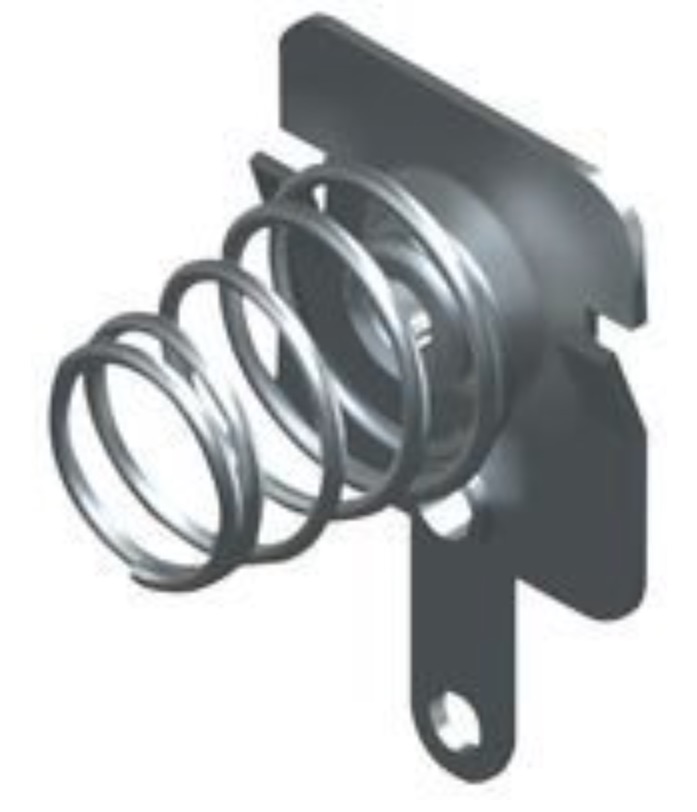
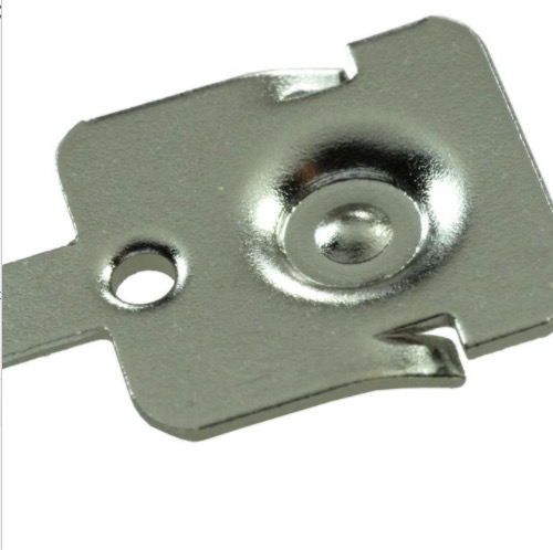
I know I asked a similar question on TRA a long time ago, and while I cannot find it now, the recommendation was to use a contact like this one:
As for other building tips, you might have to provide a few more details, like what hilt you’re working with and what you’re trying to cram into it. Are you printing your own chassis? What kind of printer are you using?
thanx for the info, i was looking at similar items but didn’t know if any were recommended to do the job well?
it will be a total custom job from the ground up.
it started when i saw how technology has evolved from a simple torch with a plastic tube on it to what we have now and my inner child had a “bobby Duke” moment and said “I want that!”
so i perused the custom shops and added what i wanted / liked.
needless to say the prices were eye watering and my inner child cryed for a few day until i thought… could i build one???
the project was born! since then i have reaserched the inner workings and roughly how hilts are made.
i settled on your board as it was the best in my opinion and the options almost endles!
i’d like to say that i’m a bit savvy when it comes to making things (cough) but i need a bit of a nudge with this.
i have an Ender 3 v2 for printing parts that i need.
the chassis ideally will hold…
v2.2 board
battery
kill switch
2 single pixels and crystal
i’d like to keep the battery removeable as it may sit for long periods unused and for easy charging and hot swapping of cells when out showcasing it.
dims are 36 ID (hilt) x 154mm (this would be good if i can fit this in as im planning on using a 40mm driver so would like the space for that.)
i’m planning on machining the hilt from alloy for the final product and most the internals will be 3d printed.
for the moment i’m printing my concept ideas in stages and will finally piece them all together when im happy they all work and i like the exterior design.
Well, if you’re building from scratch, then you decide the dimensions.
You can put a surprising number of batteries in a 3-foot hilt.
I have no experience with building crystal chambers though. As amazing as they are, I really don’t care what my sabers look like on the inside. I’d rather have a bigger battery than a crystal chamber.
In your case, you have fairly large internal diameter, so fitting some things right next to the battery should be easy, but I kind of assume you were doing that anyways.
Make sure to plan enough space for the wires, they always end up taking a surprising amount of space in my designs.
TBH i was thinking of ditching the crystal chamber to either gain more space or reduce the length of the hilt slightly. but i kind of like the idea of a cut out on the hilt to show it off
the wiring i totally get, I’ve done some dummy runs with a printed hilt and apart from the battery issue, that was the biggest headache.
i was hoping to have enough room to mount the battery and board on top of each other as you suggested without cramming it all in too much.
i thank you for your advice and will post my designs up to see in anyone has a better idea of how to do it or if im missing something that could cause an issue.
I have made 3 custom chassis and each time it was the wires that stuff me up. not only that make sure you decide which wires you’re going to use in the build. if it is a tight build with no need for flexibility I would go with PTFE. if you do need flexibility and you got an open type chassis then silicone is your friend.
with a crystal chamber make sure you have the wiring diagram setup first and then try to accomodate your chamber wires from the neopixel and consider how you are going to attach your neopixel to the crystal chamber and consider how those wires, remember your going to be using at least 3 wires, 2x22 awg AND 1 x 30 awg. those wires will need to go all the way to the board.
also consider how you are mounting the speaker, will it be, inhilt adapter + crystal chamber + soundboard + battery holder + speaker holder or inhilt adapter + crystal chamber + battery holder + soundboard + speaker holder.
the difference is that you will need to consider the wire lengths and the types of channels you will use and those diameters. take in consideration the type of wire as well. with ptfe you don’t want it to bend as it will put stress on the solder joints and they can come off (especially the 30 awg trust me I learnt this the hard way).
p.s. everything I learnt, though I rage quit and bought a chassis however with time, patience and $$ you’ll get there.
Thanx for all the advice, it’ll really help.
I’ve got most of the design down just adjusting minor things then it will be 3d printed for me to check all is well to make it a functional item.
I’ve got stranded silicone wire coming with 8 colours so will be all colour coded.
I’ve really enjoyed this project as I has so much to get involved with and the community is also top notch and so helpful when I’ve had a question
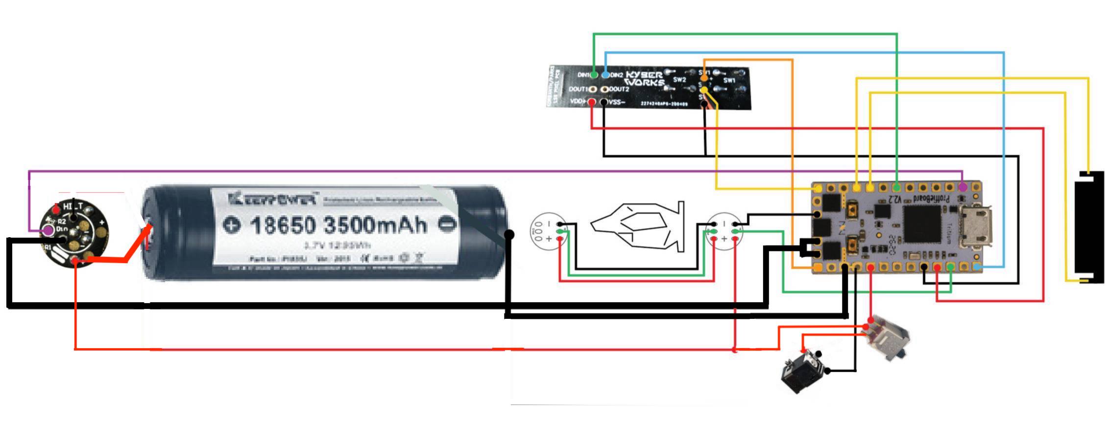
thanx for the wiring diagram NoSloppy.
I did wire everything up on the dining room table and got used to programming the board for blade styles and sound font so I was happy and comfortable before putting it into a hilt so I wouldn’t struggle.
but this is defiantly a big help
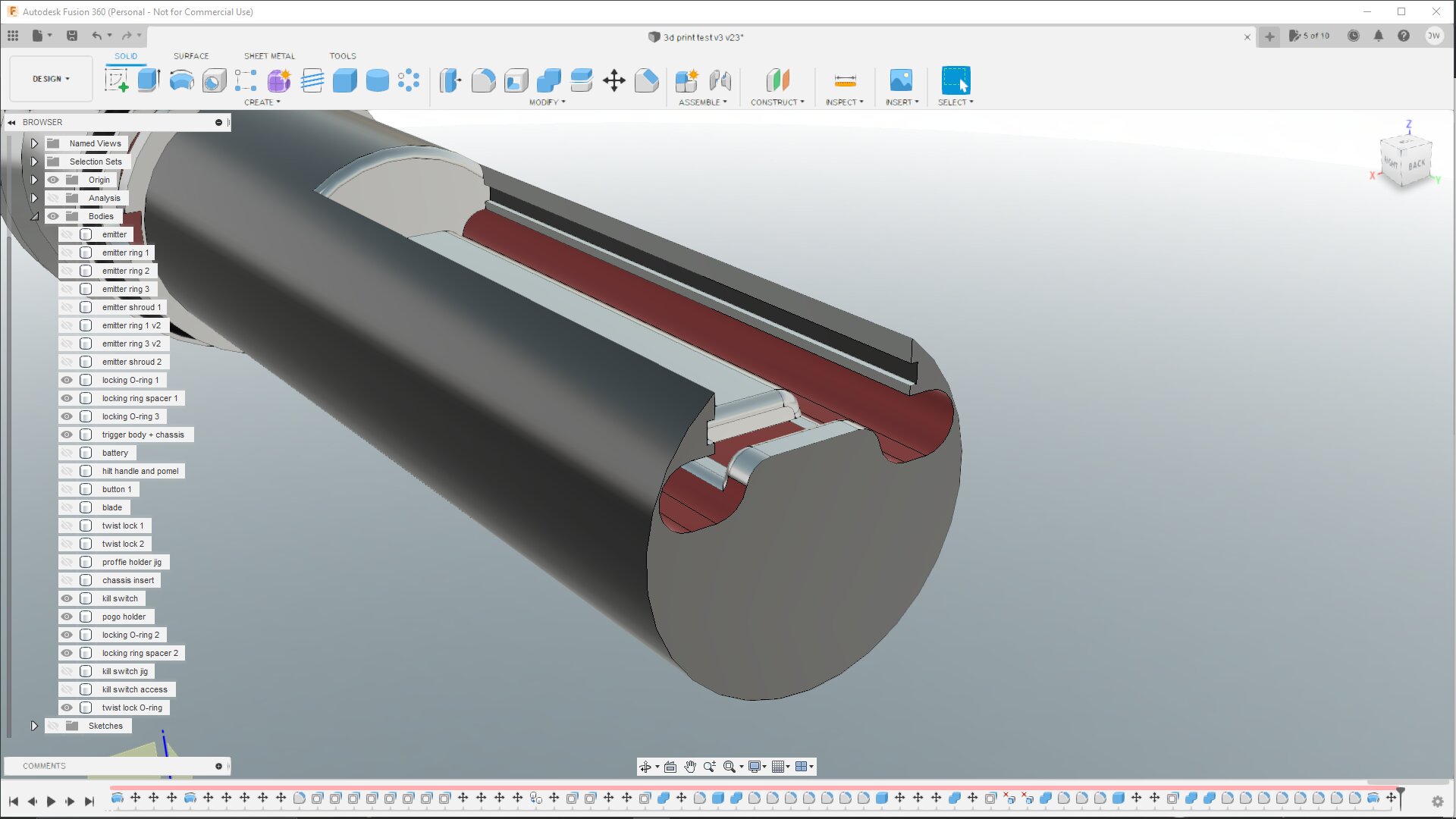
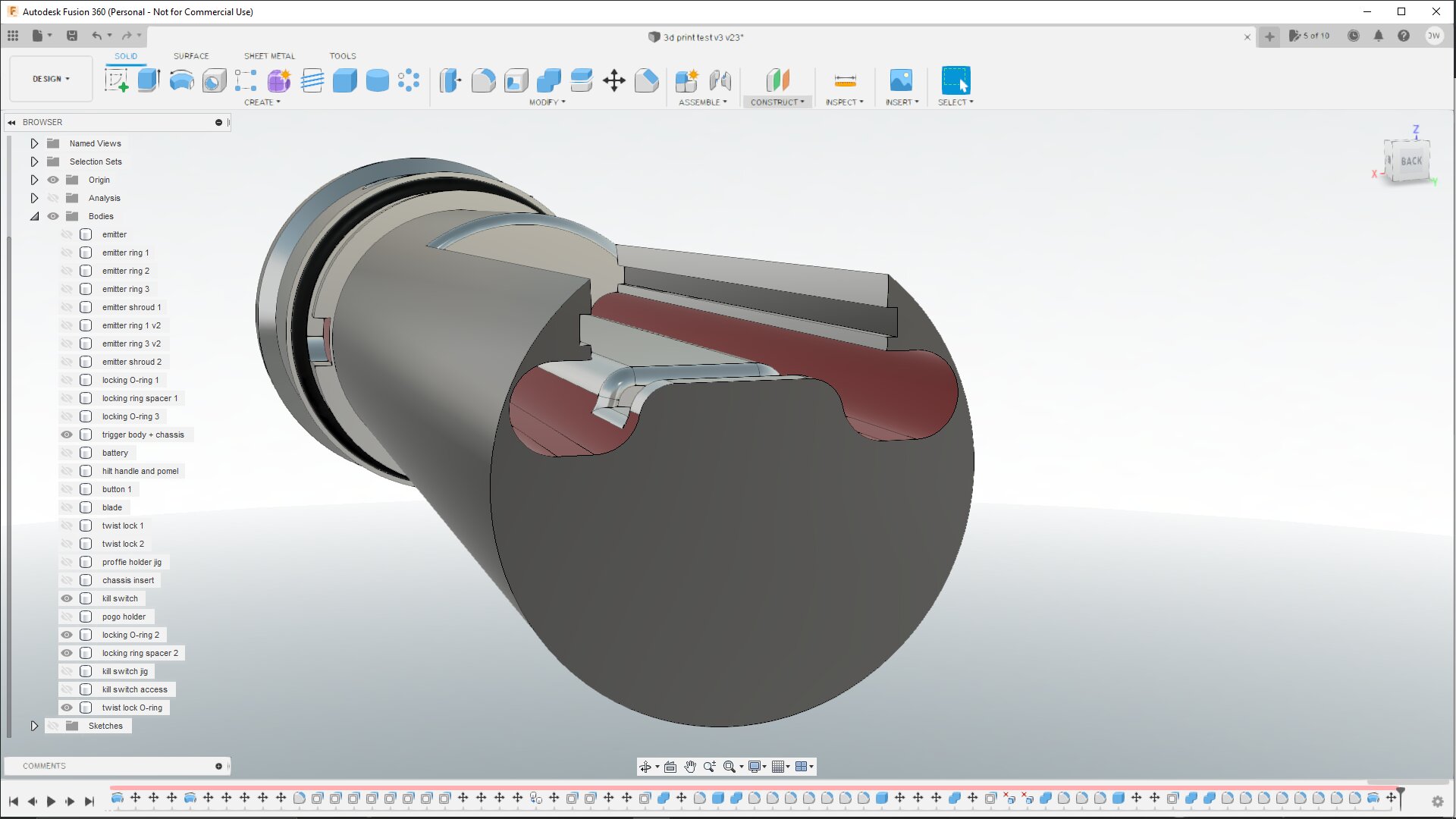
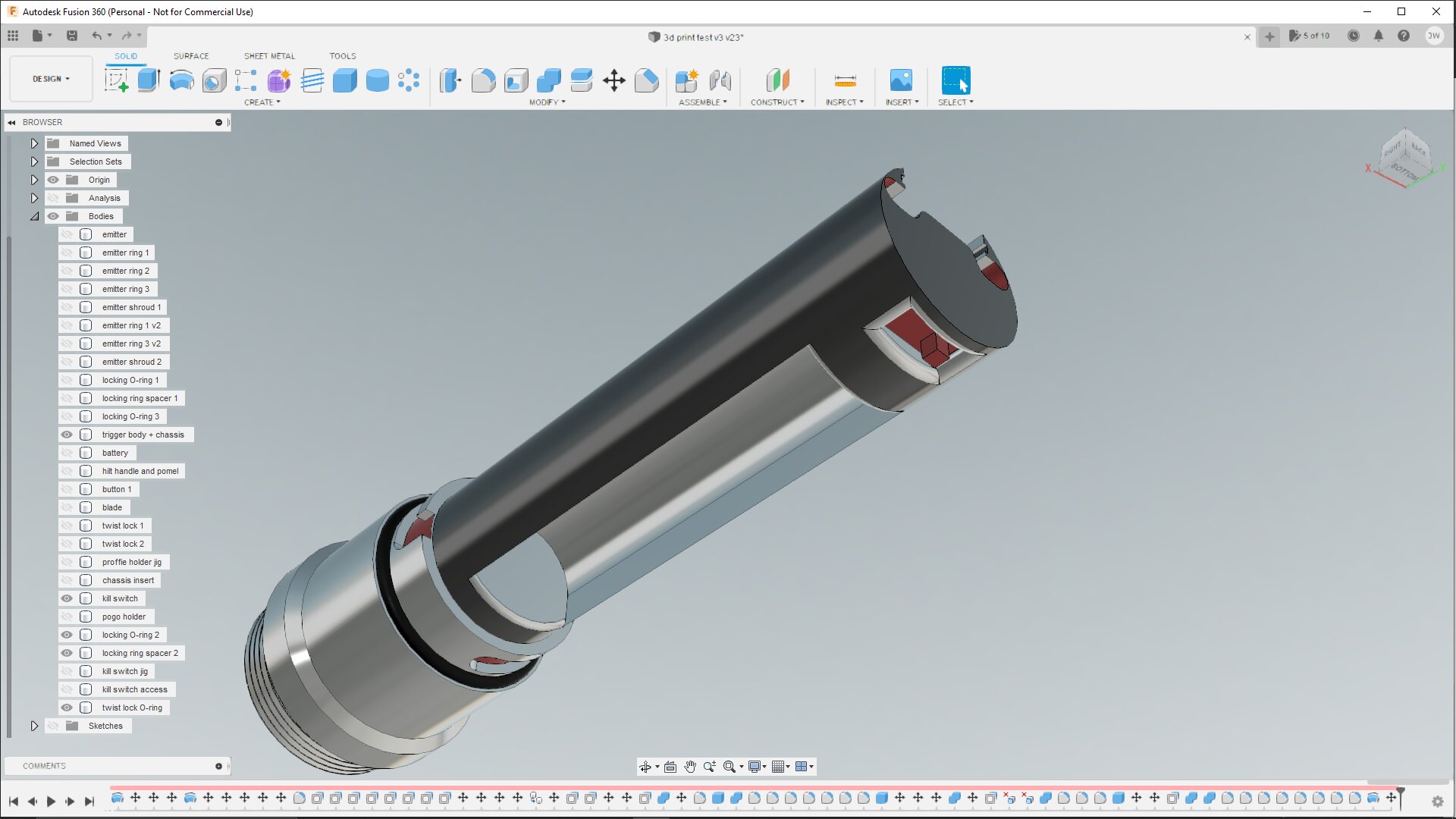
update for my chassis design, I’ve taken everything on board and had a look at some that are available to buy and I think it could work?..
it was a bit of a squeeze as my ID I’m working to is 28mm (I got it wrong in another post)
the proffie board will slide in on the captive rails to hold it in place and I think the wiring space should be ample enough but I’ll know for sure when the 3d printer has finished printing it.
kill switch is also in quite a nice spot to get at (I think)
I think the sliding in is a mistake, because it either means that you will have to wire everything in place, which is pretty hard, or you have to make your wires longer than they need to be, which takes up extra space.
I don’t have a great answer for how to hold the board though. In my chassis I make a cutout for it and then I make a wide 0.5mm groove around the hilt to for the kapton tape I use to hold the board in.
thanx for the feedback proffezzorn and that’s a great 3d drawing, I can see you have lots of space for all your wiring.
the groove is only 0.5mm so shouldn’t be too imposing on the board.
I’m planning on soldering the board first and then sliding it into place and feeding the wires down the wire slots. (might be a bit fiddley but if it works should give me a nice finish.
time will tell.
While I like the concept of the slots, I can speak from experience that if you just leave the bottom lip there and clear the upper part through to the top, 4 small dabs of E6000 on the corners holds the board just fine, with added benefit of a minute amount of shock absorption.
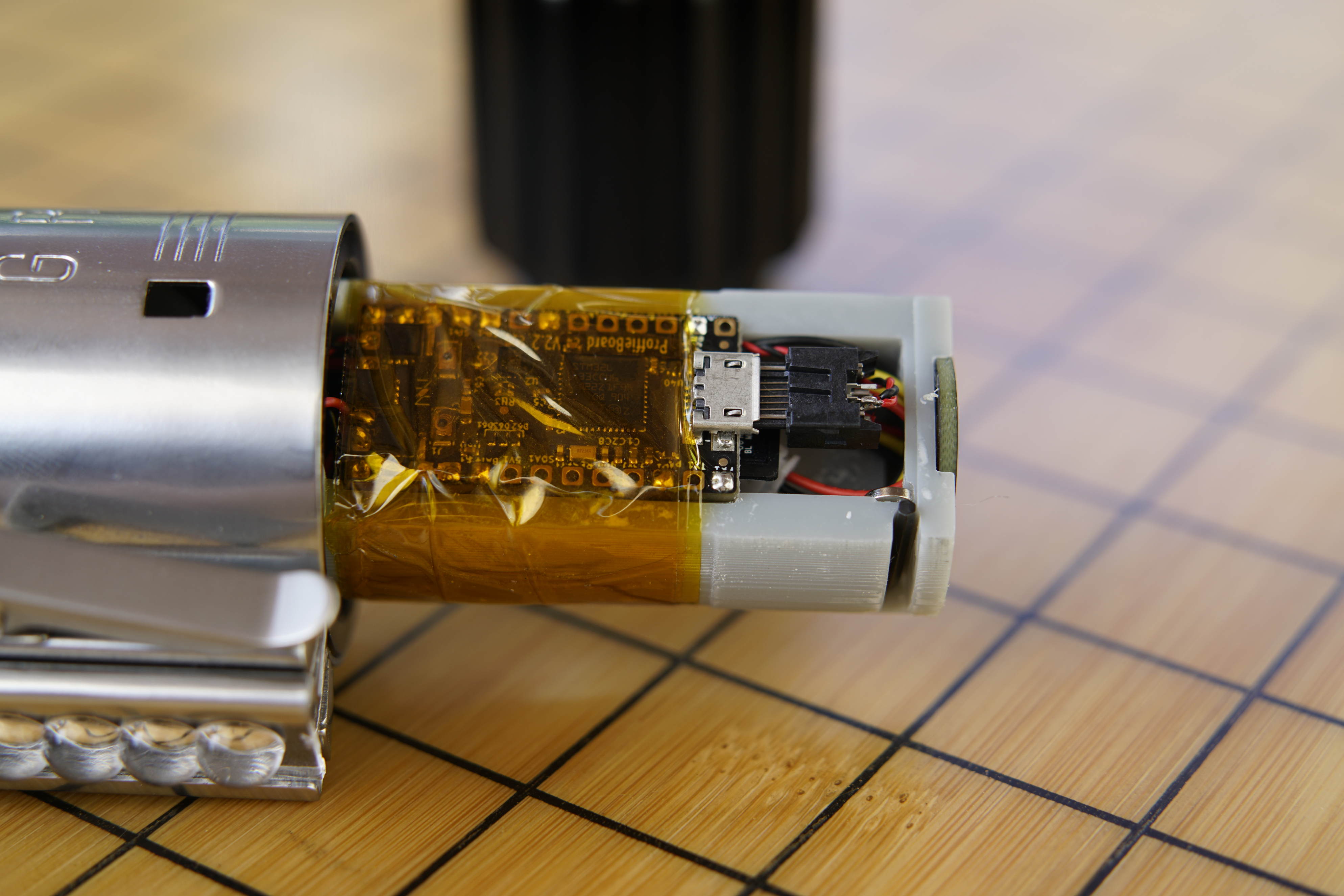
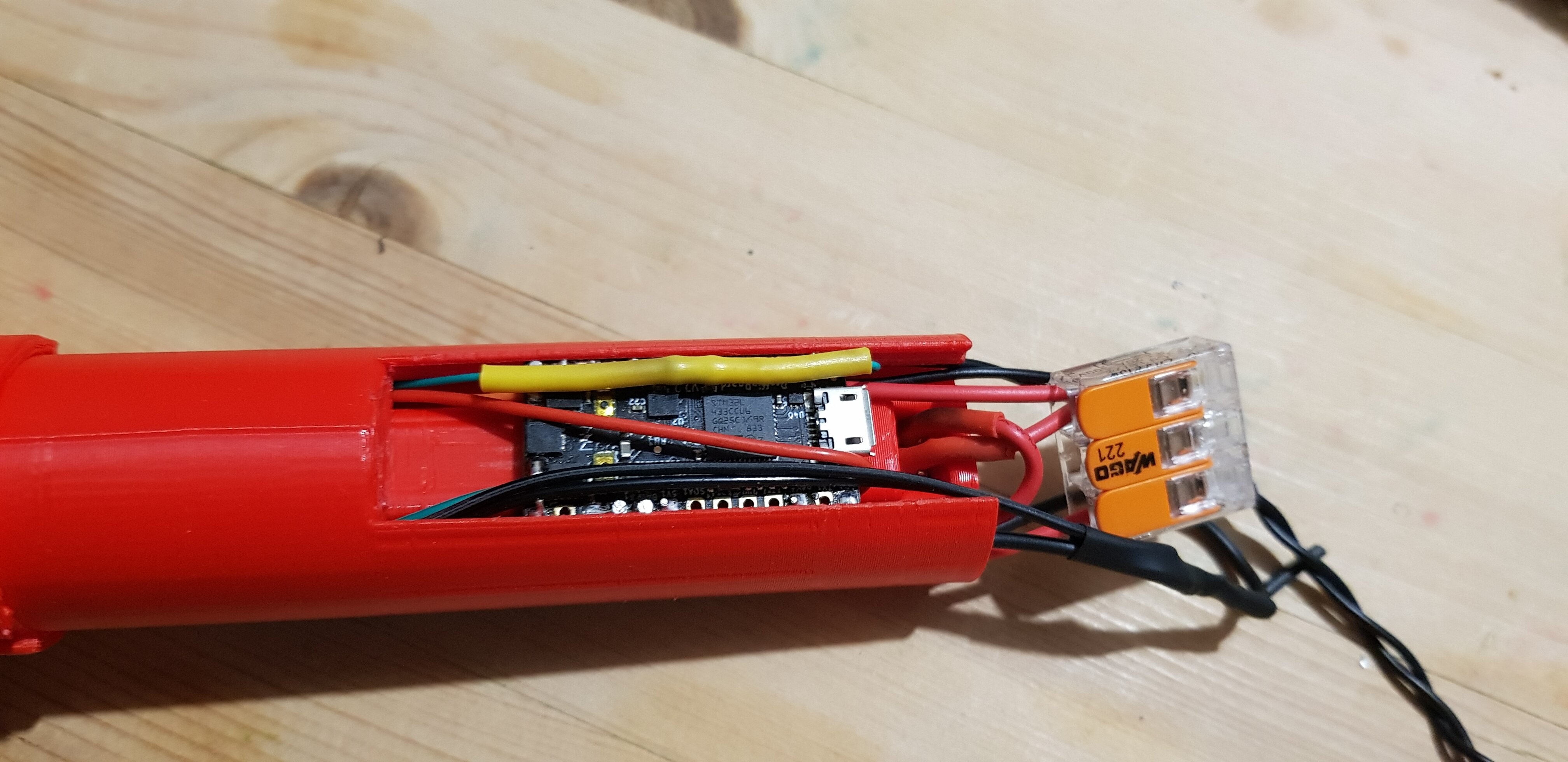
its a little clunky but it proves most of it works as expected.
it has some minor changes to be made (wiring space the first) but it is mostly there so i’m very happy.