Anyone here familiar with pcb design? I am using kicad here.
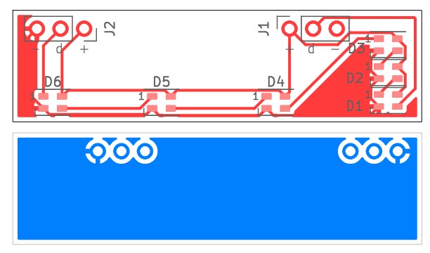
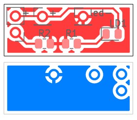
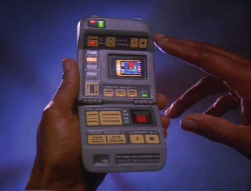
I have been working on my Tricorder project for a bit now. I have some pcbs designed to allow installation of neopixels for each light on the prop. I have 6 pcbs, all (except the lower pcb) use Batt- for both front and rear pours.
Front 1
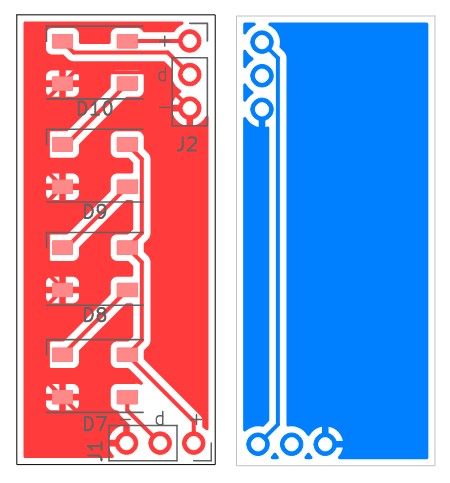
Front 2
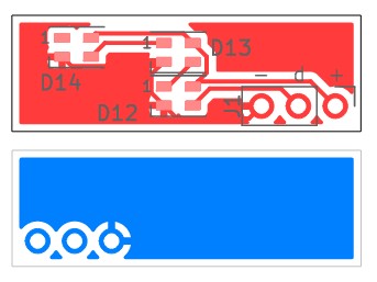
Buttons
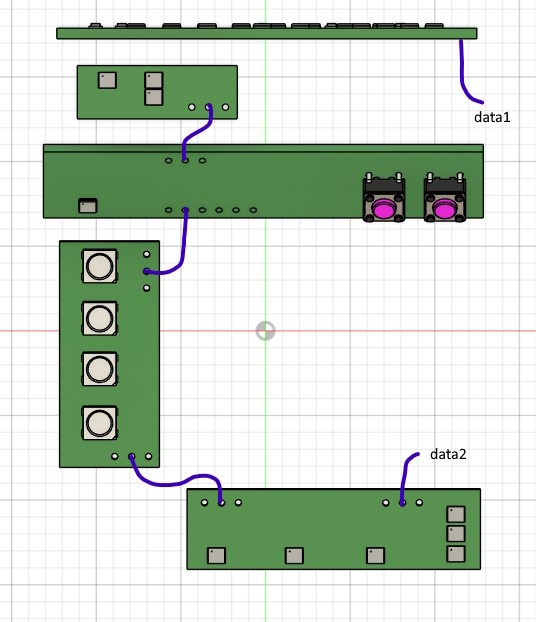
The Data, Batt+ and Batt- all jump from board to board. First off, is this a viable idea? Pretty sure it will work. Most of the neopixels are 2020, with 4 front pixels being 5050. Any reason I couldn’t mix the 2 types of pixels with the same data line?
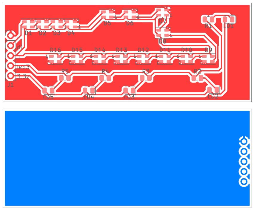
There will be a series of smd ww leds for backlighting on the front panel, these will be controlled by the proffie. And a small pcb for the lower door illumination with 2 red leds, also controlled by the proffie.
Next, do the pcb designs look viable? Anything you would change? It will be powered by a proffie 3.9 if that changes any considerations.
Here is the overall wiring/signal concept if that helps.
Very cool.
Not my favorite tricorder, but still very cool
First of all: Having the +/-/data jump from board to board is absolutely fine, but you may want larger traces for + and - if the number of LEDs get high enough that the total current warrants it, and there is no reason why you can’t mix-and-match different size pixels, just don’t mix RGB and RGBW, as proffieOS isn’t very good at that sort of thing…
Now for some questions/comments/feedback
Is there a reason you don’t just join the two front PCBs together? You can probably put some of the smaller PCBs in the “hole” to prevent waste.
Have you considered adding mounting holes? How will the PCBs be held in place?
Do you need to use the small SMD leds on the bottom? Why not make those neopixels too?
You might want to add a delay circuit (similar to the one in my TD) to the reed switch to allow the proffieboard time to play a sound before it turns off. The delay circuit is just a few capacitors, a resistor and a pFET. Doing this also reduces the current through the reed switch.
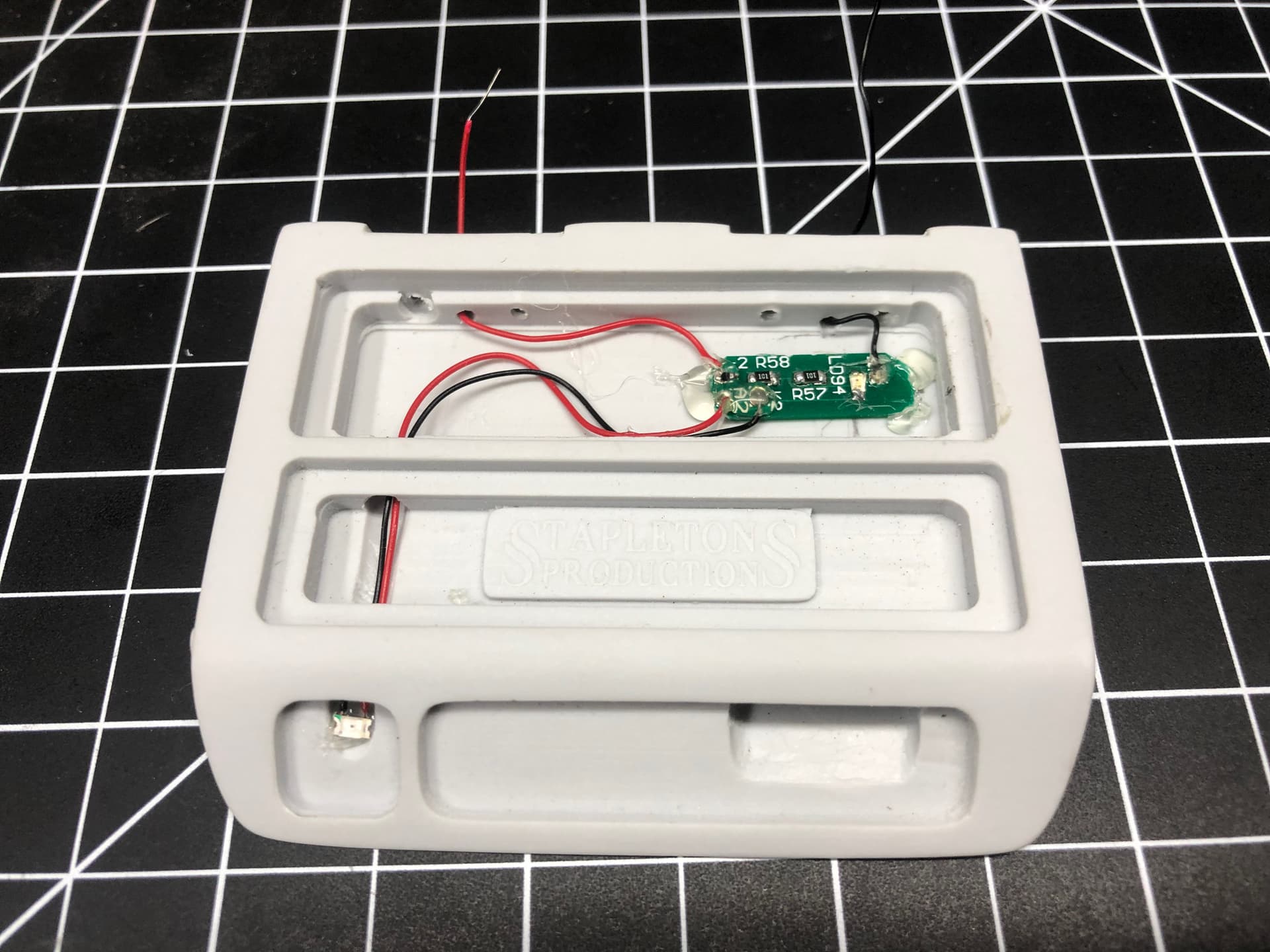
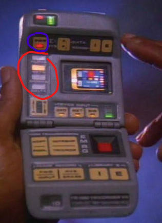
I forgot to mention the tricorder 3d model seen here is one I found that looks close. Its actually going in a Stapleton resin Mk VII.
As for your questions:
Yes. Cost. I initially had one big board for the front. As it progressed, I decided to upload to oshpark to see the price. $26 per 3. Not the worst, but I have other things to order. As a test, I broke them out as seen. They were $4 each. Much cheaper, so here I am. (an “L” shape board came out the same price, so oshpark sq in calc is overall, not board sq in)
I hadn’t really considered mounts holes. As I said, its going in a resin model, so its hard to add that. Otherwise, probably E6000.
Reason is they will be using brass hinges as conductors. I am basing my build off some that have been done with gmprops electronics kit.
That is a great idea. I will have to look over the TD files. While I do like working on projects like this, including circuits. I actually know very little about electronics design. I think I just like building/soldering/etc. So, I may need help with this.
On this particular version, they are not illuminated.
I think you can avoid most, or maybe all of the cost if you create a small panel where the small boards live inside the cutout for the L shape. Either way, oshpark is cheap, so it would seem that getting rid of the extra cables would be worth it.
I hate glue.
Interesting, (Makes me want to cut a hinge in half to get data across…)
The idea is simple. You have a pFET that controls the power. A small capacitor bank charge up when the switch is closed to keep the control pin high. A small resistor slowly drains voltage from the capacitors, so when the switch is open, the capacitors eventually drain and the pFET turns off the power.
Let me rephrase: Shouldn’t the lights on the left side of the screen be buttons?
I will look into panelizing. Doesn’t look very clear as to how to accomplish it.
I agree, and it certainly doesn’t “feel” premium to use glue for something like this. Bu seems to be what people have to do to affix the pcbs in the chassis. The stapleton body is pretty well made and even on the inside. maybe I can see if I could make a chassis for everything…
See here for the typical build glue, I think he was using hot glue. Star Trek Tricorder Mk X Build | RPF Costume and Prop Maker Community
I have a wiring diagram I will post in a bit to see if I am on the right track. Thanks
If you mean the ones circled in red, then I don’t think so. I understood those to just be backlit indicators. If you mean the one circled in blue, maybe, but because I think I only need 2 buttons, the two on upper right seemed like a good fit.
Mostly you just cut-n-paste the boards into another project. The tricky part is creating little connectors which can then be cut and removed.
Resin can also be difficult to glue properly because it’s a cross-bonded plastic. Most glues do not adhere well to cross-bonded plastics. Making a chassis of some soft seems like an interesting idea.
re: 5 Yes, those seems like they should be buttons to me.
I also have a stapleton body that I need to install. I just haven’t gotten around to it.
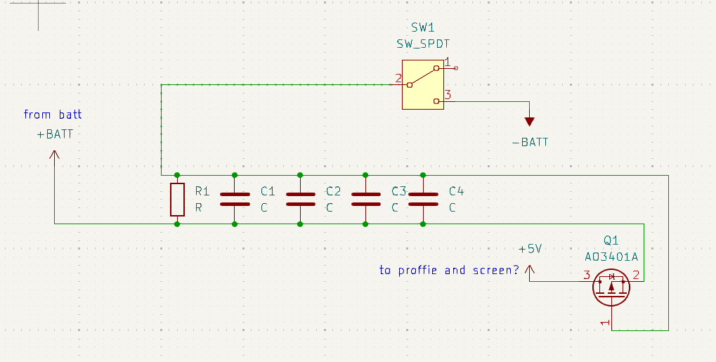
Hey @profezzorn, here is a schematic for delayed power off. Am I on the right track? What values might I need for the resistor and caps, same as the TD?
Very cool, that makes it easy.
Just don’t do a frame, cut-n-paste and go!
I think that’s right.
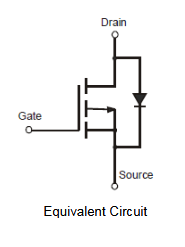
I have hooked up FETs backwards more times than I care to admit, so please double-check that the pFET you’re using matches what’s in your diagram properly.
I used 22uF capacitors and a ~400k resistor if I remember correctly. I calculated about a 30 second delay. It ended up being shorter, but still worked great. (I really only needed a couple of seconds.)