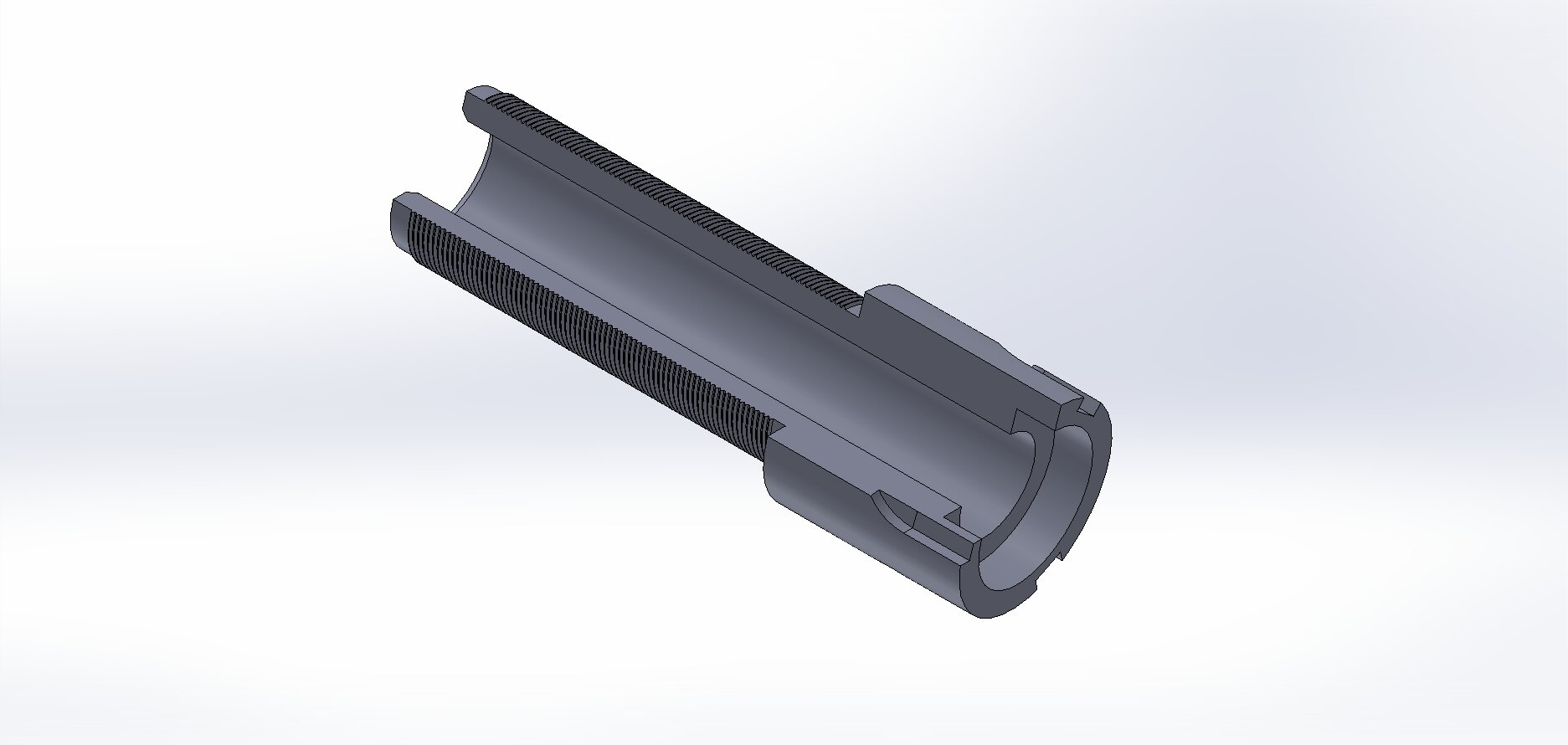
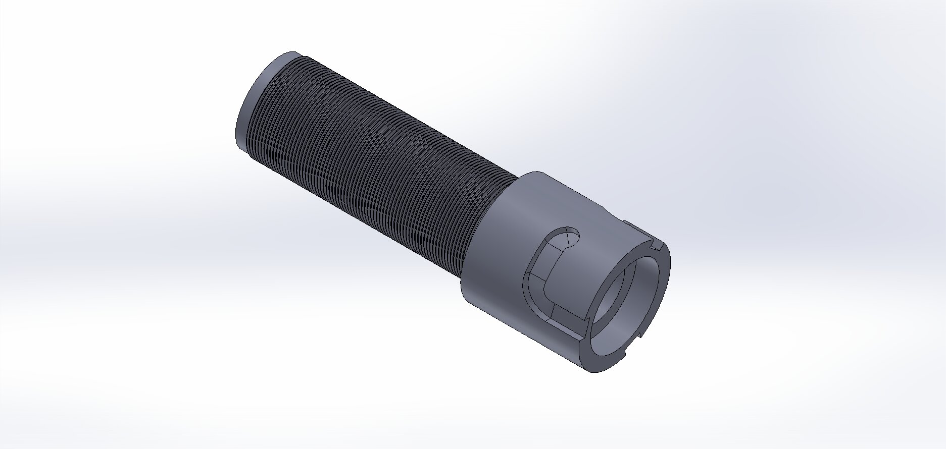
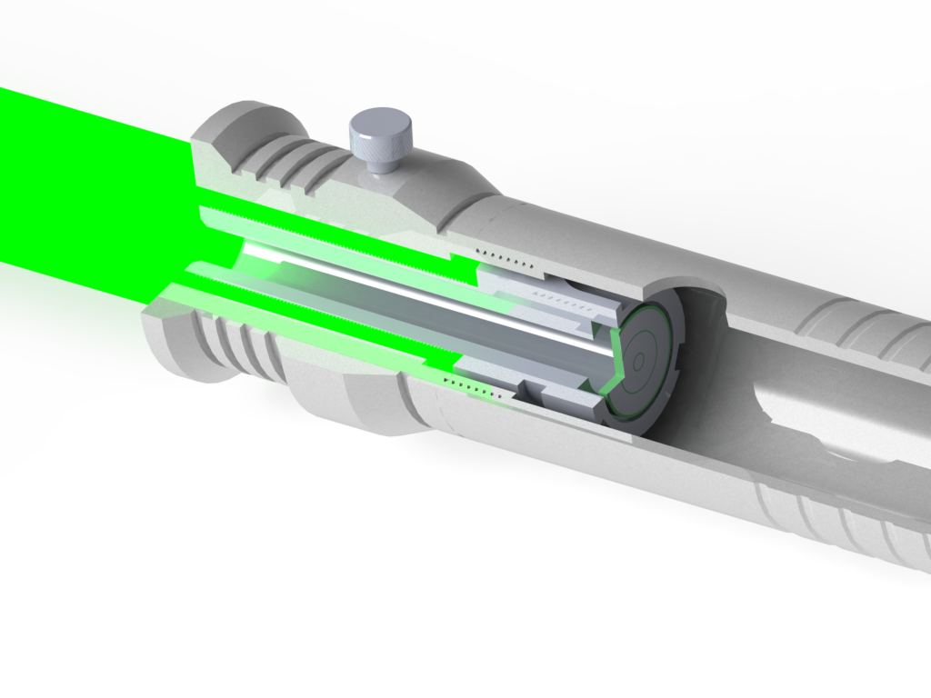
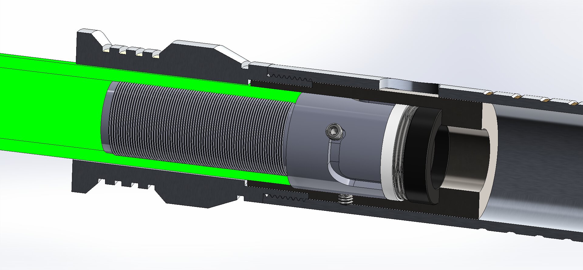
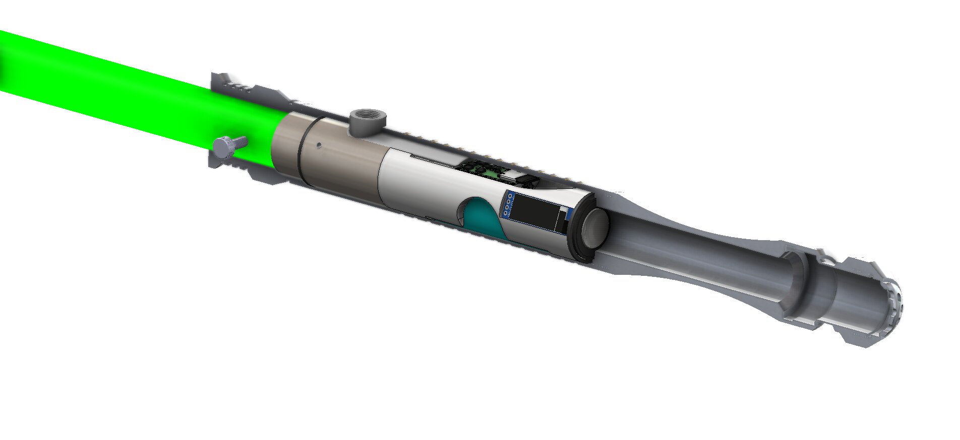
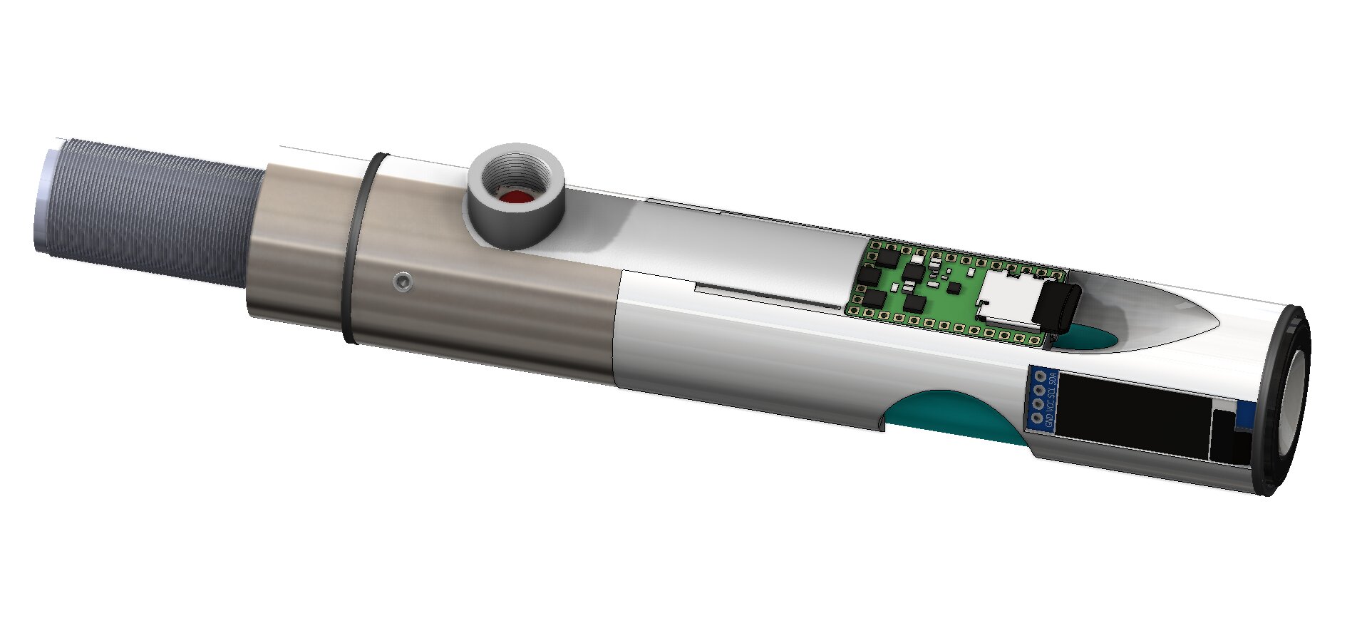
I’ve been working on some models over the last couple weeks. Idea is that we would be able to insert the blade into the hilt, compress a spring washer, twist and have it lock into place. See below images.
I’m designing it with McMaster Carr parts number 95289A314 (extended tip set screw) and 7756N193 (stacked wave disc spring), as well as with the intent for it to work with Shtok’s NPXLv3 blade and hilt side connectors. I don’t currently have a model for the blade side pcb or adapter, so if anyone has one that is reasonably accurate, please let me know!
While the initial design isn’t going to REQUIRE a thumbscrew, it may prove necessary, so I’m going to leave space for it.
The plan is for these parts to be compatible with the 1.24" MHSv1 from TCSS.
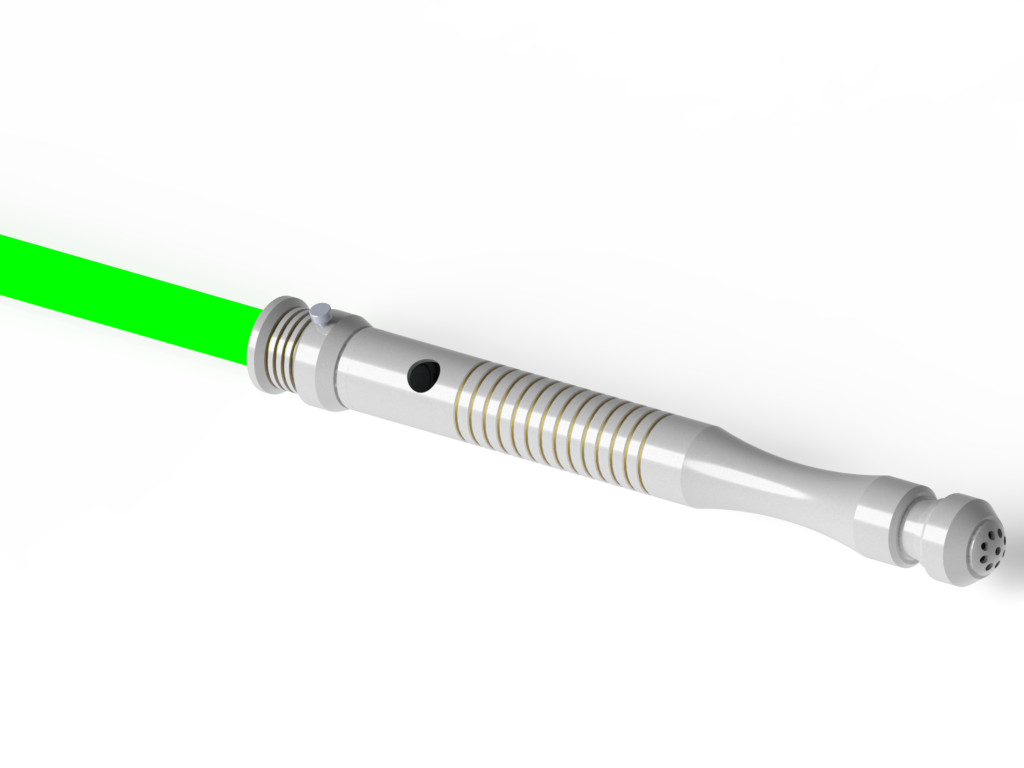
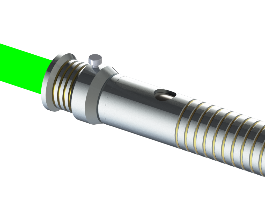
Here are a couple more images, cause solidworks does fancy rendering. SHINEY!
Interesting.
How does the part hold on to the blade tube?
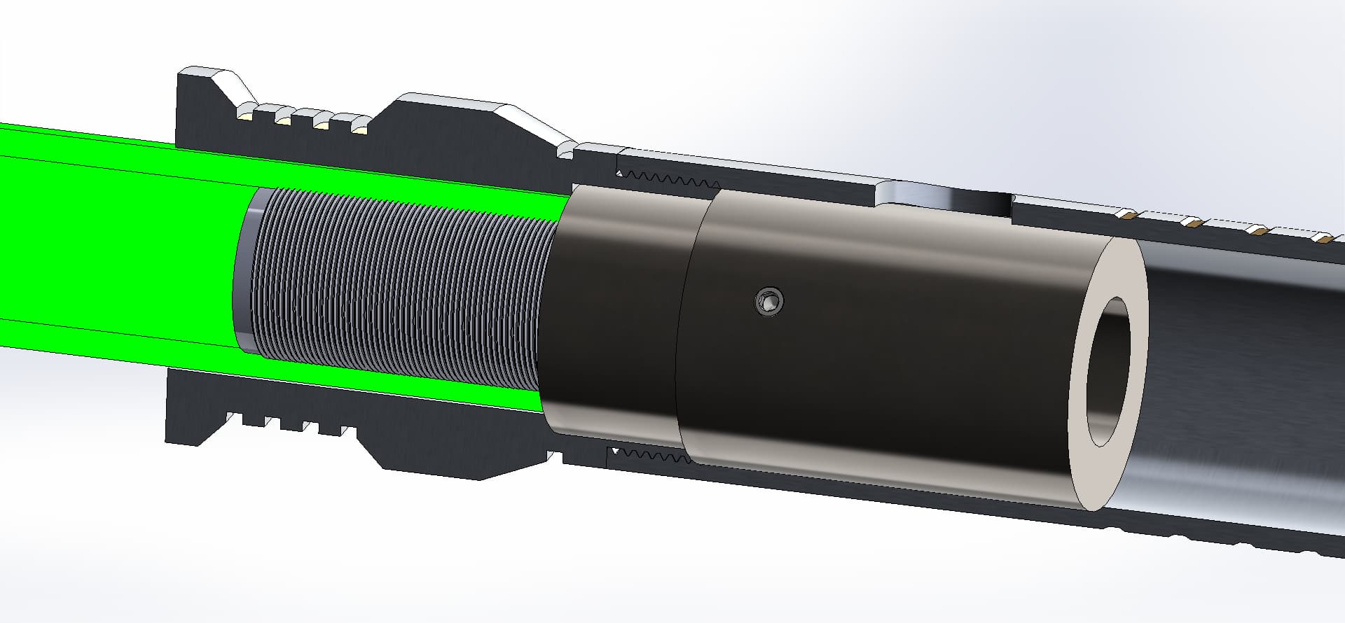
My first try will be 40tpi threadding, reinforced with epoxy if needed. Ideally it would just be a threaded connection, but frankly I don’t think that will hold much swinging around, so epoxy will probably be needed. I don’t want to make the threads too coarse, as the bigger they get, the more material will be removed from the blade walls, and the weaker it will be.
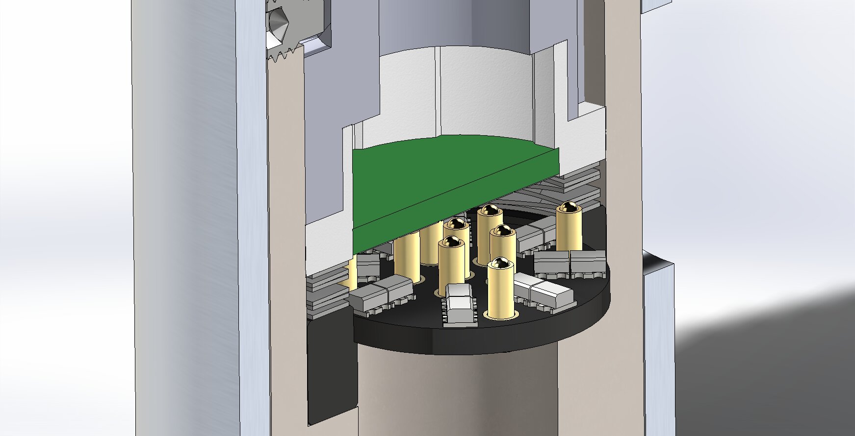
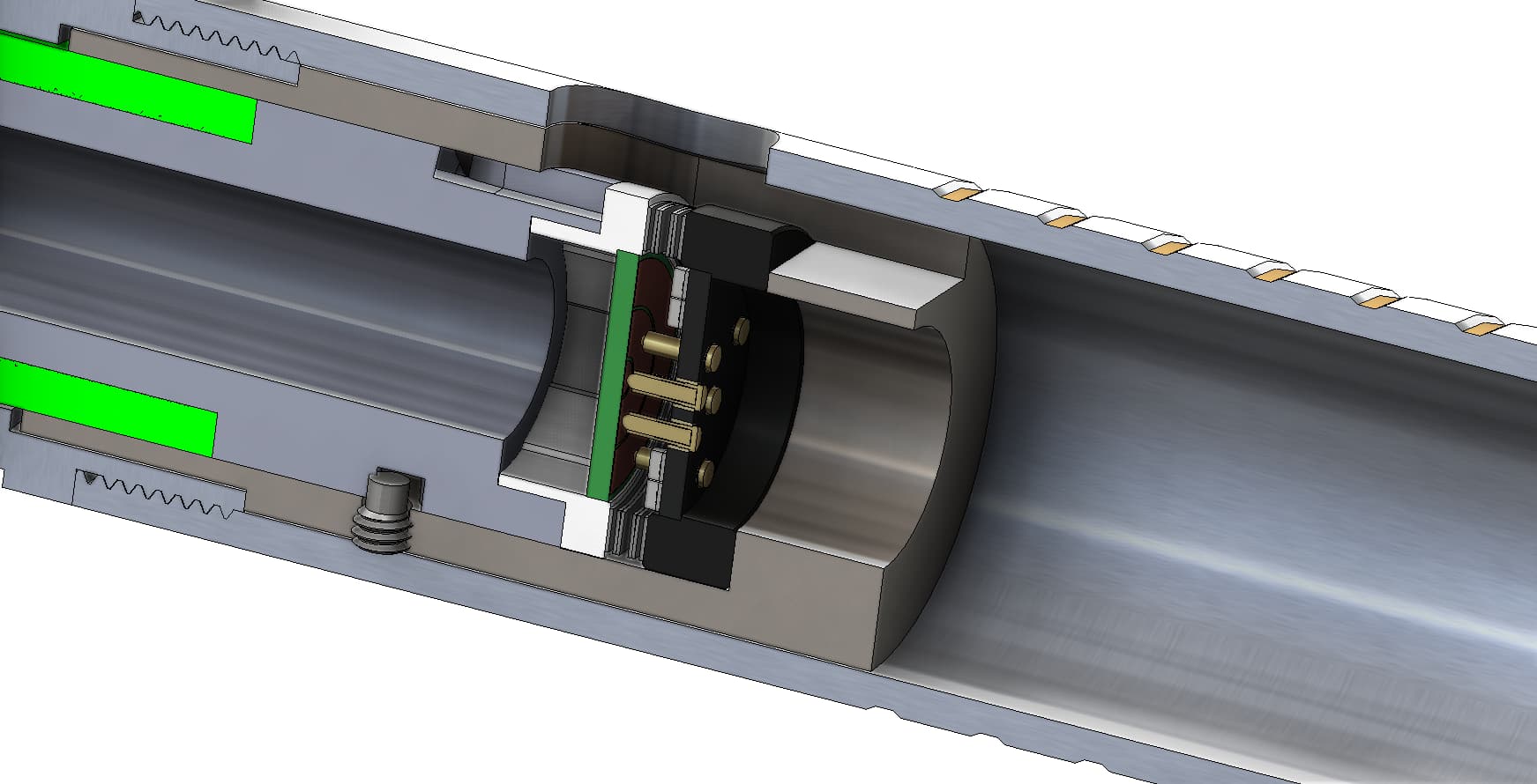
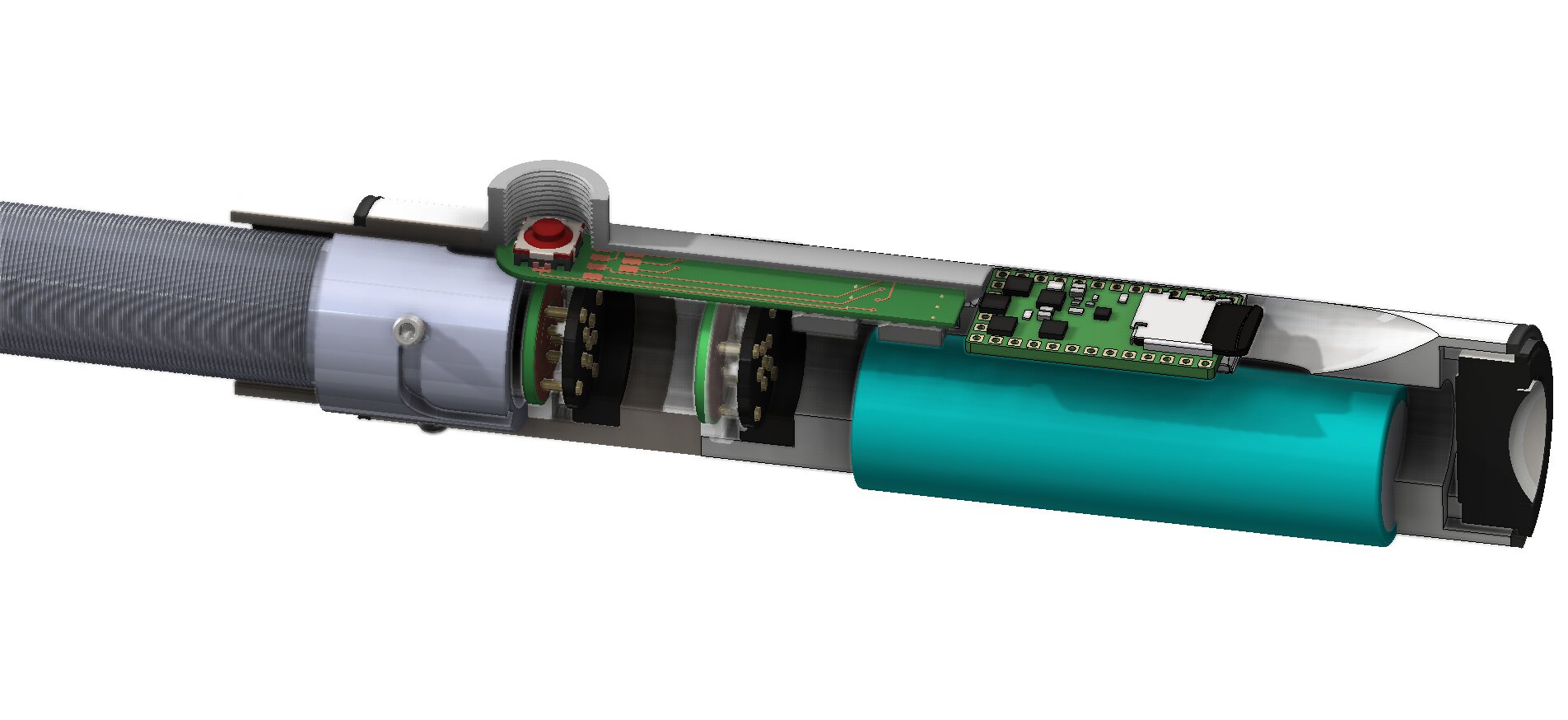
Here are a couple more renders after doing some work on the hilt side component. I still need to figure out how to secure it to the body, probably with screws… but it would be nice if it were part of the chassis. I’ll have to think about that.
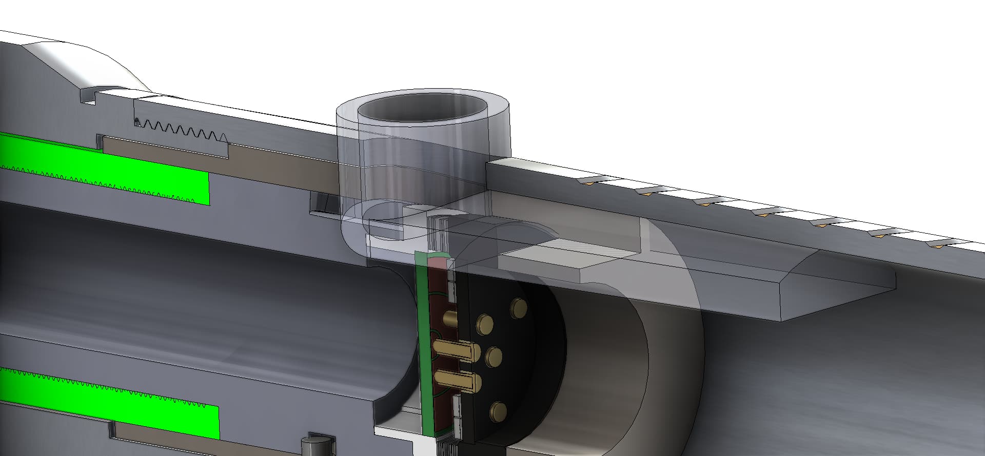
Another note, currently the button hole is blocked off. My plan is to cut out a groove in the hilt side component, so that a small board with battery spring contacts can slide into position, with a double tac switch permanantly connected to the body… somehow.
What if you cut the inner cylinder into six separate “fingers”, and each finger had a round peg on it which would fit into a hole drilled in the tube. The fingers would then have to bend to be inserted into the tub, and the pegs would have to be pushed in from the outside if you ever want to take it out again.
Not sure if I’m describing this well…
Threading polycarbonate has a bit of history, and from what I understand it doesn’t generally turn out great.
I think I’m picturing what you mean, and it might be workable. My original reason for using fine threading instead of just glueing it in was to give more surface area for the glueup. I think I have an even better solution though. Those little extended nose set screws come in lots of tiny sizes, so I can just use one or two of them to secure the tube to the adapter. I’m just a little worried about the loss of strength and stress risers at the holes. I might do some simulations to see what it looks like.
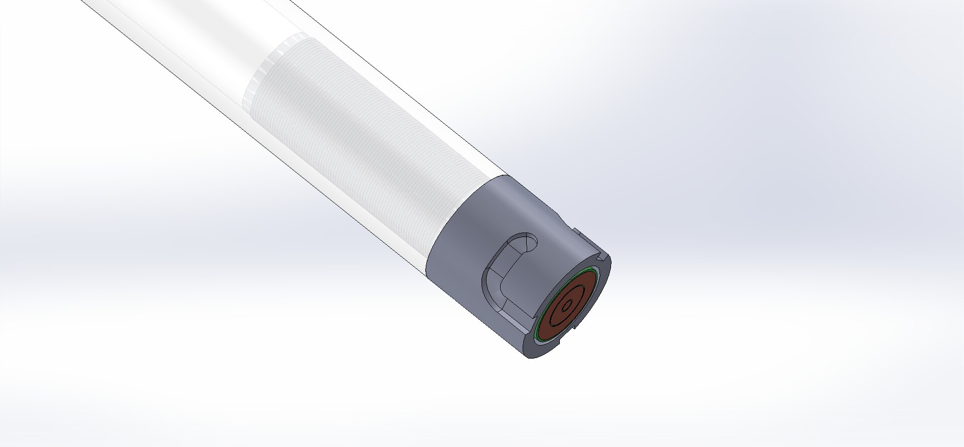
one more image for this weekend. added the compressed spring washer. still need to model and add the blade side pcb holder, and fix some dimensions.
Not sure if you’re still looking for those models of the PCB and adapter, but here they are: Shared Part Models - Google Drive
@mcarcher Thank you! I did make a couple quick stand in models, but now I have something to compare the dimensions against. Thanks!
Edit: It’s worth saying that I do plan on sharing my full design along with a BOM once I have it finished and working. I’ll be posting both the solidworks files as well as step and stl files, so anyone who wants to can modify them to their hearts’ content. 
1 Like
Neat idead. I may have to do that to my saber blade.
More images after some additional work. I had to fix the dimensions because stuff wasn’t lining up correctly.
Next step is to build a chassis and figure out how to connect the two. I also need to figure out the best way to connect the hilt side adapter to the body of the saber, so it doesn’t just spin around when you try to connect the blade. I’ll probably end up just using some M3 button head screws… but i’d prefer to have a solution that’s not visible on the exterior of the saber. and requires minimal alteration. I’m open to any ideas you guys can come up with.
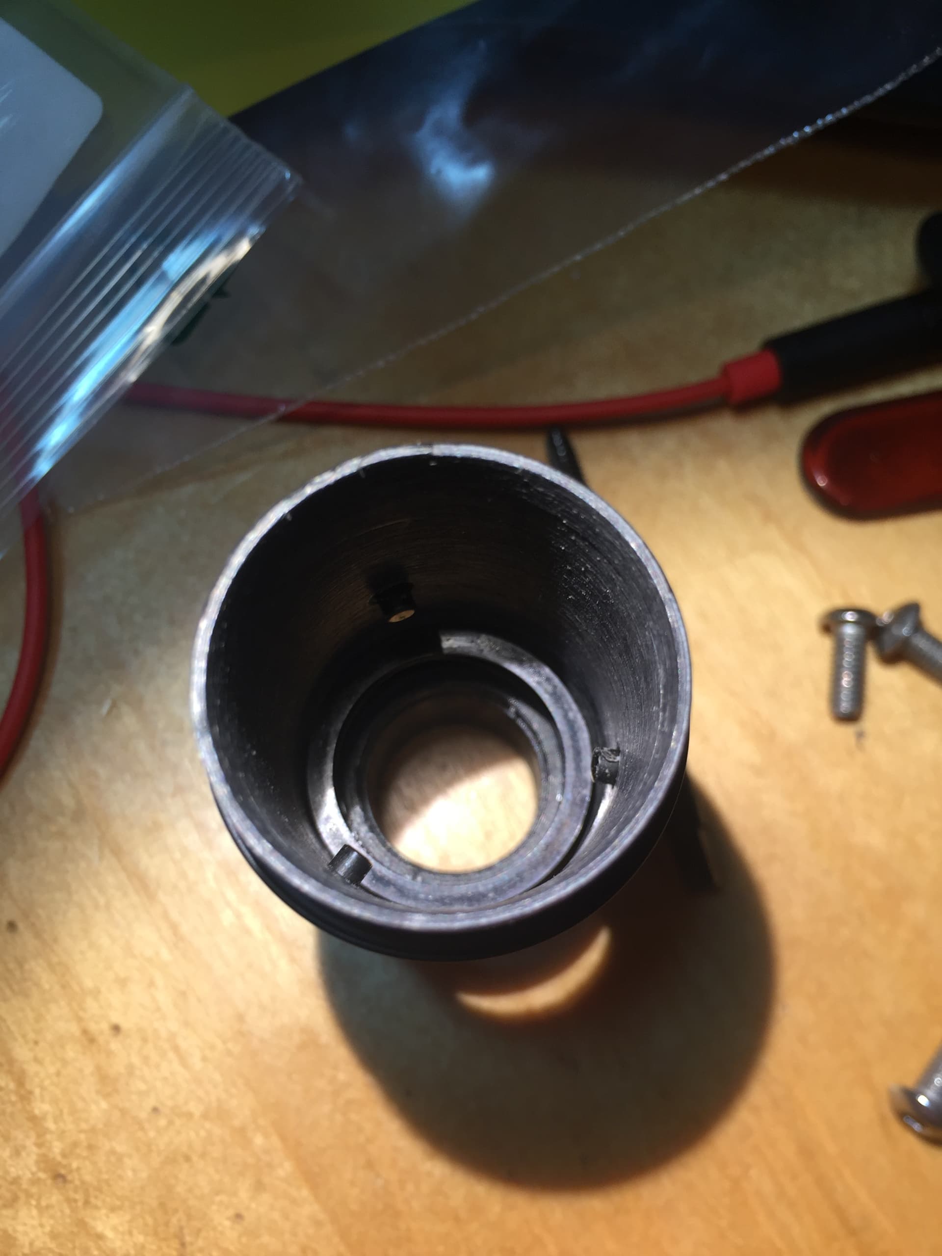
EDIT: Oh yeah, I need to change how the blade side adapter connects to the blade as well. I’ll be using some of those extended nose set screws like in the image, but probably smaller ones. May keep some of the threads, but I want to cut the threaded section down from 2" long to 1" long. I’ll be 3d printing all the parts before cutting stuff from metal, just to test fit and see how stuff works. May be able to get away with ABS 3d printed parts, but I kinda doubt it.
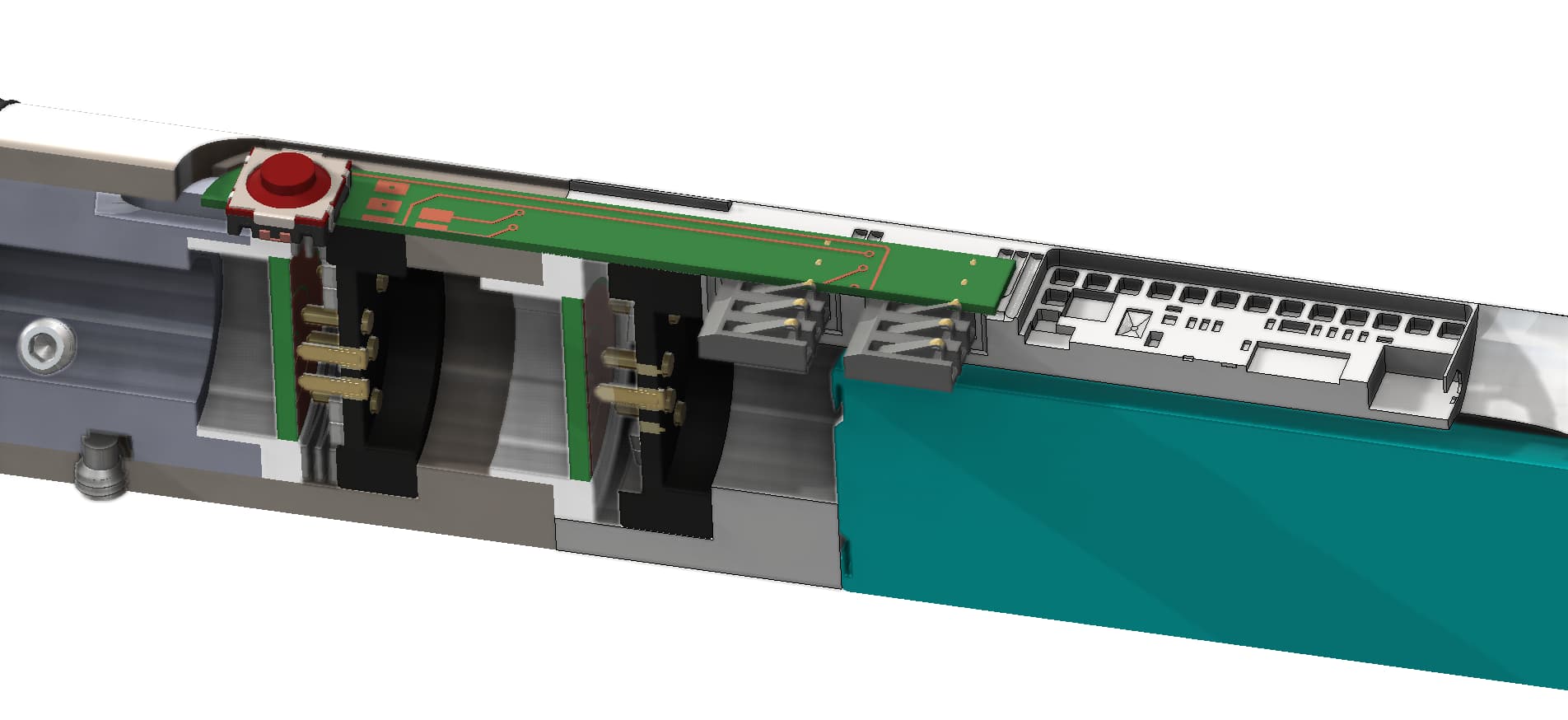
Here’s my idea for the buttons:
I have a kr duo switch, like this:
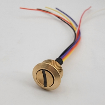
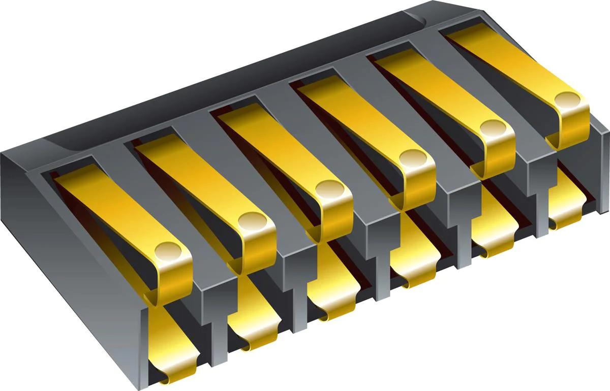
So I use that transparent… button thing? anyway, I use that to hold the kr duo in place, and run the wiring inside it (somehow), and terminate at one of these thingies (with fewer pins):
One question for anyone who knows: If I have two tact switches, can I use a common ground for both, so that I only need 3 wires, or do I have to use two wires for each? I haven’t started looking into the button wiring and stuff for my proffieboard yet, so I’m not sure how it should be set up.
Yes common GND is fine. Do it all the time. In fact, you could even do common + Power instead and define them as PullDownButton
pull… down… GAH don’t mess with my mind like this man! I’m not ready for fancy stuff like that! 
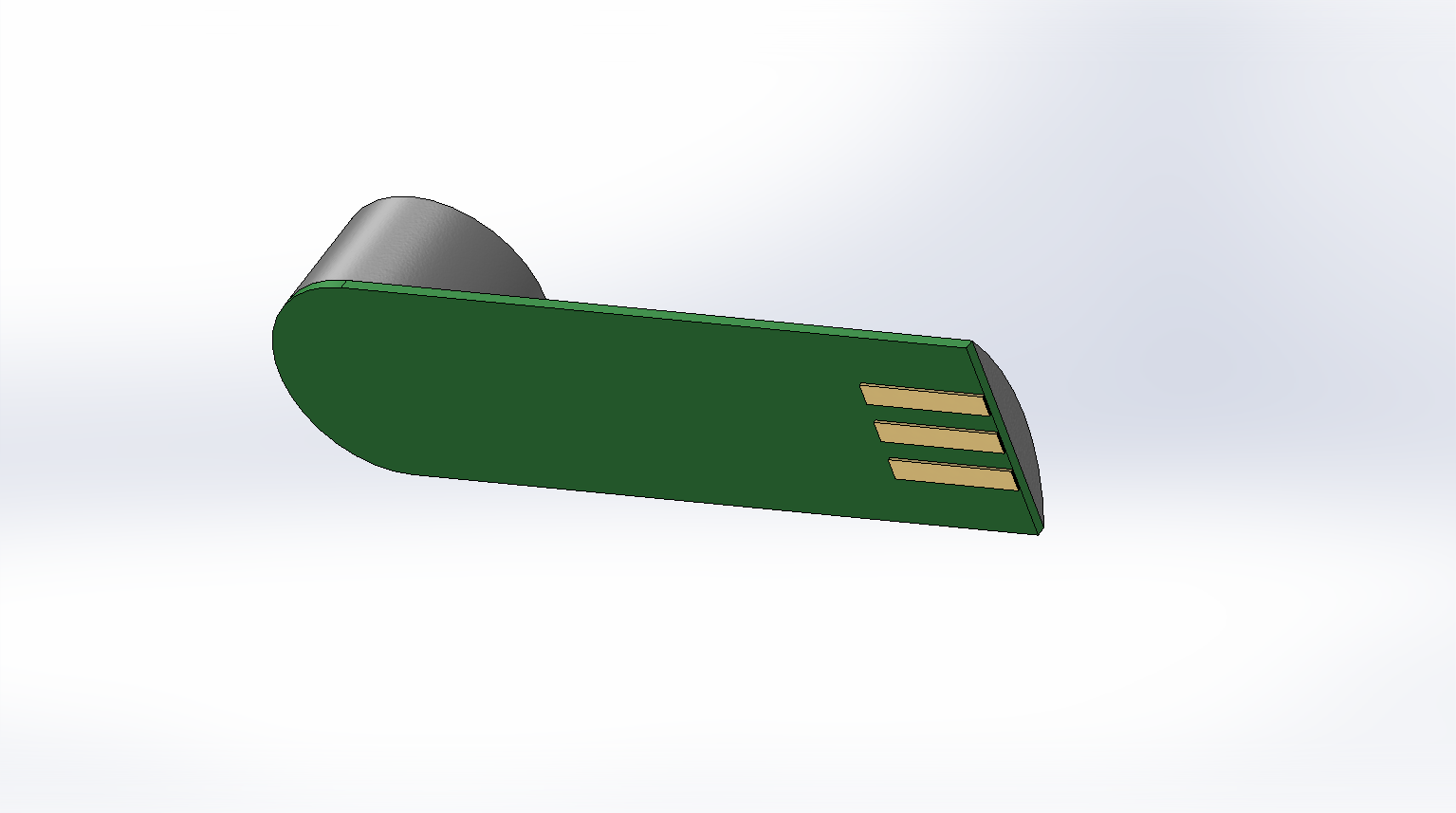
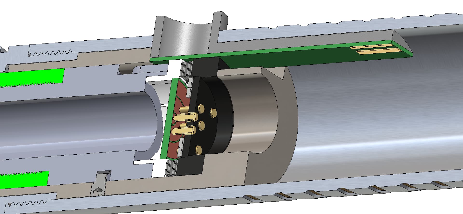
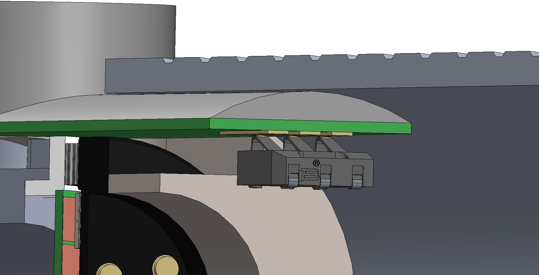
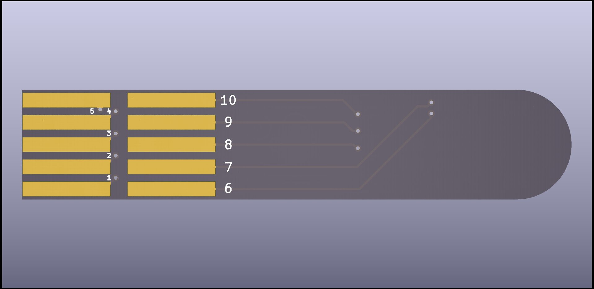
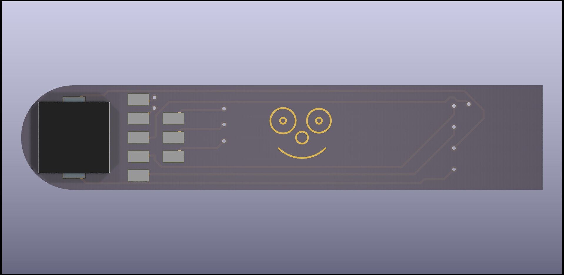
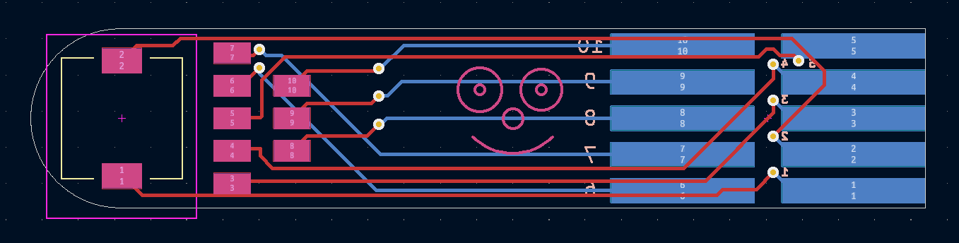
Update: I’m 3d printing prototypes now in ABS. looking at the button-thingy, it looks like I might have enough room to change the bottom layers of it into a pcb, which would have female contacts for the bourne type battery connectors, so that the thingy would be permanantly attached to the body, and the chassis would be able to slide into place, rotationally keyed by the thingy, and automatically make an electrical connection with it via bourn connectors. Soooo… I wonder what we might be able to slap on such a pcb besides just a couple contacts? any ideas?
Edit: Oops, that male connector is backwards… just pretend for now, not worth posting another image over. 
Ok, so if I were to get about a hundred of these little pcbs made, it would cost me about $100 give or take. I think I’m going to go ahead and do this, so the question of what else to put on the board becomes very relevant. I suppose, if nothing else, I could add more contacts at the end, and a bunch of little and pads in a grid so that folks can make their own additions, like a breadboard…… but I’d rather have more concrete ideas. What would we need to run a wifi or Bluetooth antenna connector along the board, up through that 2mm thick wall in the button hole, and then attach an external antenna? Having an external antenna should help a ton with signal strength, and might make fancier wireless coms easier in the future. Could an antenna be wrapped around the button hole cylinder?
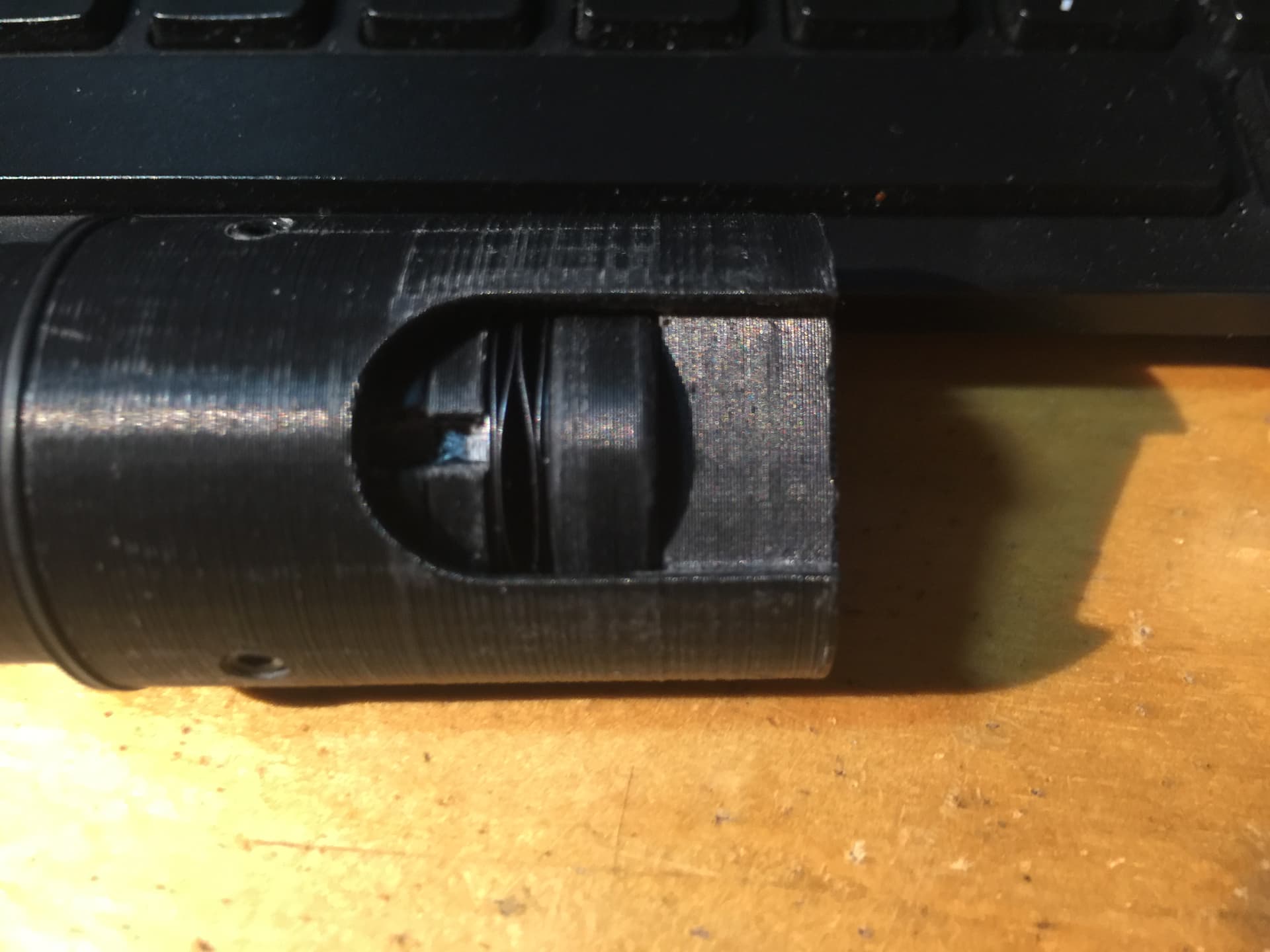
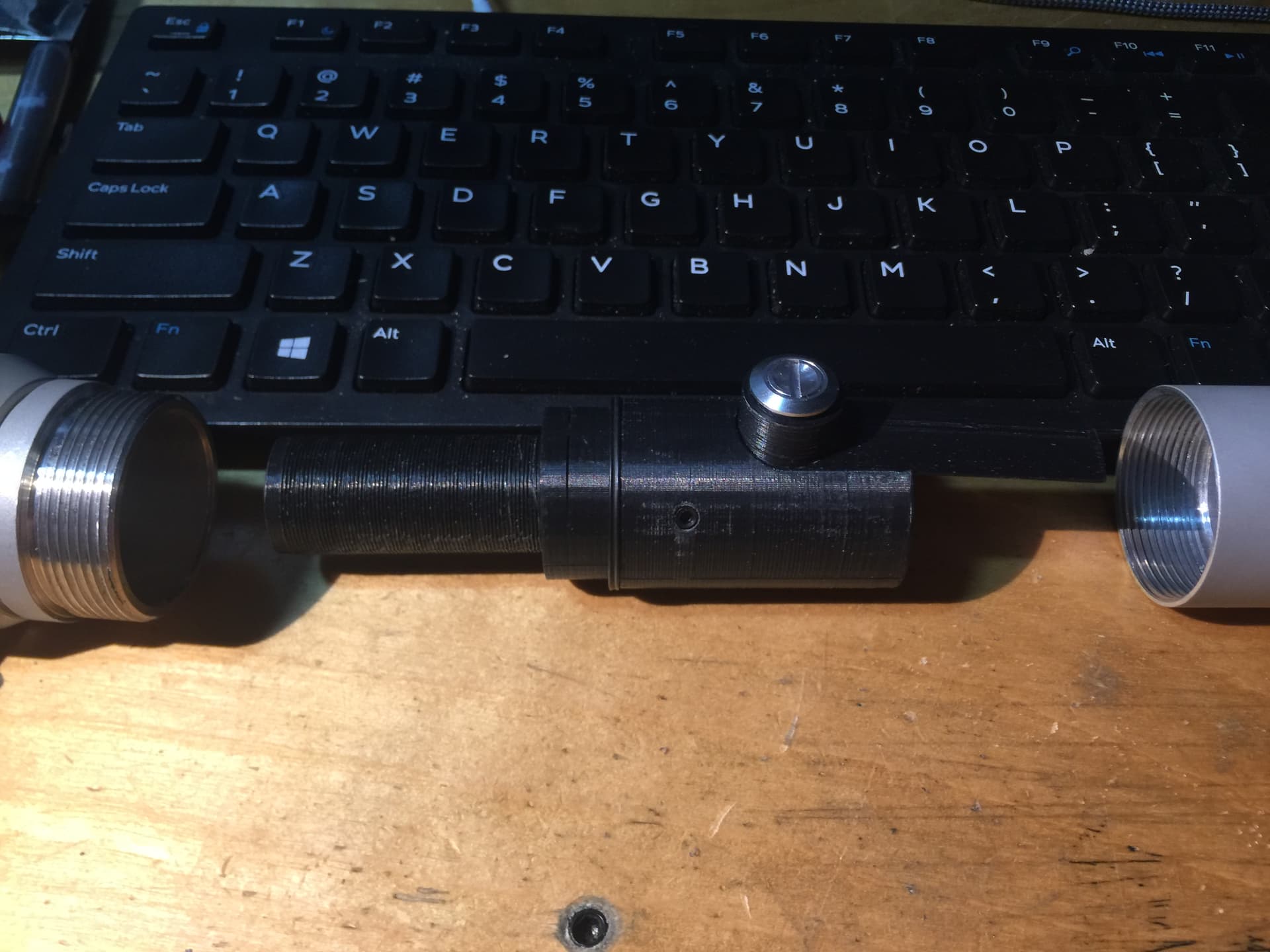
Good news, everybody! I got the first prototype printed out in ABS, and after receiving parts from McMaster Carr, I can say with confidence that this design is viable! I’ve got more changes and work I’m doing on it, of course, but the prototype works about 80% as intended. One sad note is that 3dprinting in ABS may not be viable, and the parts may have to be turned from solid bar stock, or possibly printed and then reinforced with steel sleeves. Will keep you all posted (if anyone is watching this thread, anyway. :D)
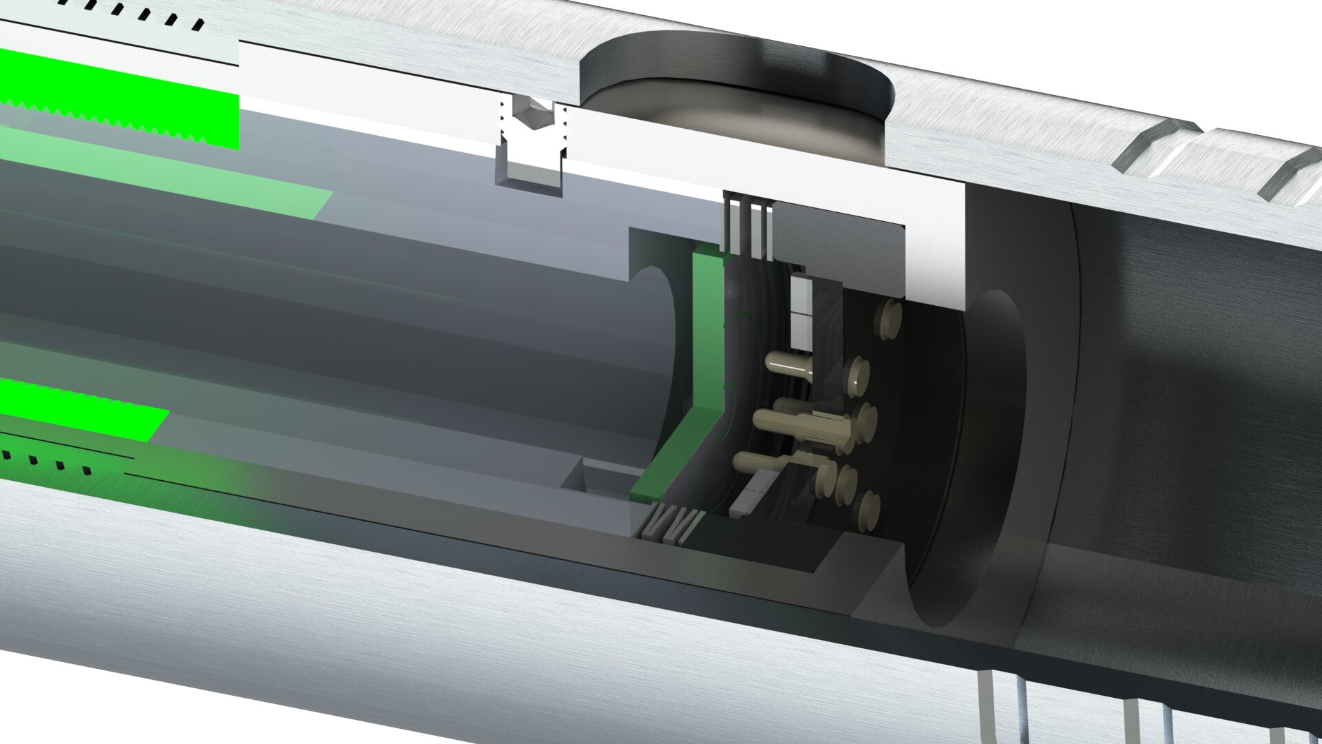
Just another image dump with pictures from the current state of the model. Enjoy.
I’ve gone ahead and ordered half a dozen of those boards from oshpark. I may end up needing a pcb for the chassis too, to hold the male connectors and to mount a rotary encoder, but we’ll see when I get stuff fitted together. I’m running out of room on the chassis to put stuff, and still need to find space for the bt module, and to route wires. My plan is to cut 2/3 circular profile grooves into the outer walls of the chassis and run the wires through them. Might even go with us insulated wires to make it look neater, but that would mean I’d have to insulate the inside wall of the saber body.
PTFE-coated wire tens to have fairly thin insulation, which saves quite a bit of space.
When you really need to save space: magnet wire!
1 Like
I was thinking about magnet wire actually, or maybe trying to lacquer bare wires myself. It’s really primarily for aesthetic reasons that I’d like bare looking wires, but thin insulated would be nice. I should have some 18awg ptfe coated wire showing up tomorrow or like Tuesday at the latest.
Edit: that big notch on the battery section, intended for extracting the battery, is really in the way. I may just wrap some kapton tape around the battery to make a pull tab, and do away with the notches entirely.
Edit 2: you know what, I’ve got an airbrush and a bottle of gold paint. I’m going to paint the Teflon coated wire gold. That’ll look nifty.