As an aside, I’m hoping that I might be able to use solidworks electrical to autoroute the wires on the chassis, but I’m not sure if it’s able to dig a channel into a cylinder or not. I need to do some more investigation on that still. Also, I managed to get the Kincad model of the pcb imported into altim. Now I just need to see if that helps me in any way, and if I can get the design back out and into kicad if I make changes.
Ok, so I’ve got an update and a request. Voila!
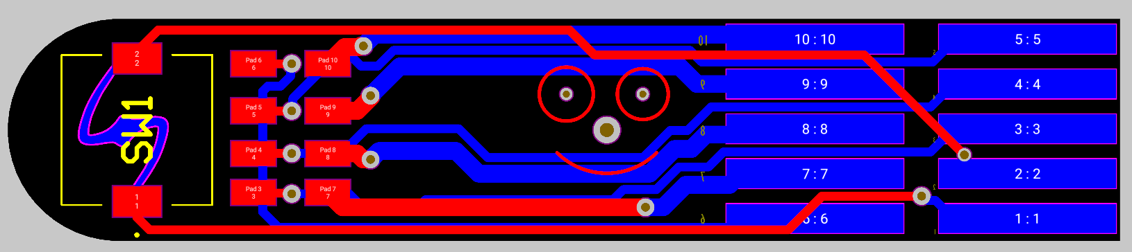
This is an updated version of the button connector pcb that enables the chassis to communicate with buttons (and STUFF???) which is permanently mounted on the body of the saber. First version is already at OSH Park (thank you Proff for mentioning them!), but I will probably get this second version made as well. The reason for the changes are to improve the current carrying capacity of the traces. In the original, I think I was using oshpark’s minimum trace width (cause I don’t know any better) but then someone asked how much current they can handle. I think the original is about 1A per trace with moderate heating, but it prompted me to take another look at the design.
Request: If any of you folks who are familiar with pcb design have some free time and wouldn’t mind reviewing the board for stupid beginner mistakes, or general advice, please let me know. I’d love to learn anything you care to share. This is my first pcb ever, so I probably made some more mistakes than just the trace width. The project is currently in Altium, but I have a web space where the project can be viewed for anyone whose email I add to the list. I’m trying to figure out how to get the design out of Altium and back into kicad, but I haven’t had much time to investigate that yet.
Anyway, I’ve got some updates on the actual bayonet adapter as well, which I hope to be able to post this weekend. The short version is that I’m integrating the hilt side connector into the chassis, and will 3d print it. I think there will be enough strength and support just from the blade holder (tcss mhsv1) to keep the blade from wobbling around, as long as the lugs can keep it in place. I may have to change back to a milled 2 piece design when all is said and done, but I want to try this first as it will be much cheaper and more accessible for anyone who wants to replicate it.
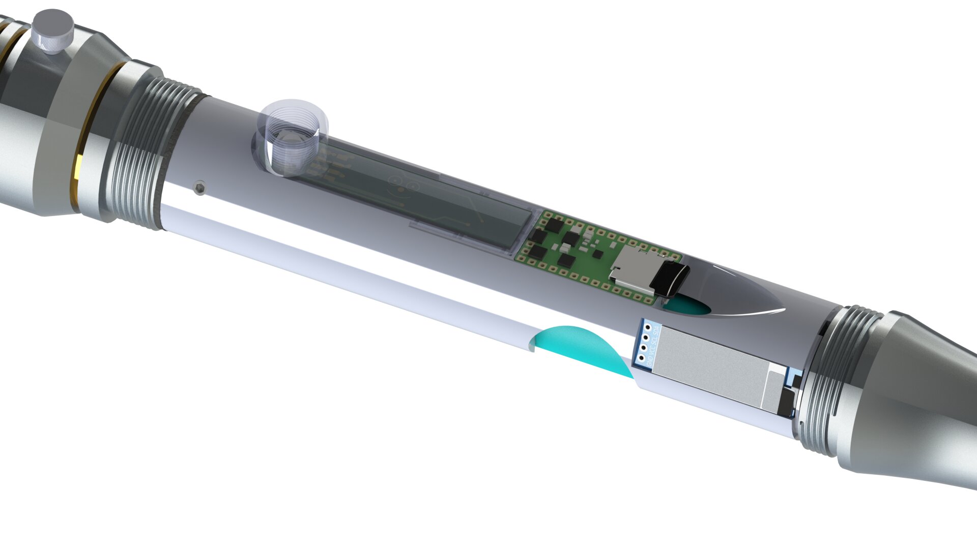
Bonus image:
Real quick update in case anyone cares. I went back and tried out a slightly different approach that was supposed to allow the chassis to be a single piece, all 3d printed. Got a prototype printed out, but some design limitations resulted in it not working as well as I had hoped. However, I’ve got a couple good takeaways:
- 2 piece design similar to the first concept is the best way to go. Better strength, simpler assembly.
- the whole design can probably be 3d printed in ABS, but if needed the section that holds the studs could be made from steel or aluminium tubing without too much machining. One turning op, one boring op, and one milling op.
- The pcb is waaaay longer than it needs to be, and I can eliminate the second NPXL from the original model easily. The spring may have to be glued to the chassis though.
- The battery connectors I initially selected, Bourn’s 70AA series, can be replaced with their 70AB series, for higher density, and I can get ten contacts in a single row of contacts, rather than the double row in the initial concept. That will allow the board to be shortened to almost nothing.
- While I’m not going to do it for the initial build, as I want to get it done in a reasonable amount of time, by using the battery connectors and the PCB, I can pass rf signals to an external antenna, AND have an OLED mounted on the outside of the saber, along with a rotary encoder with tact switch. Still trying to figure out how to put all that together, but I’ve got parts on hand to play with prototyping. I’m going to try using MMCX right angle and edge connectors to pass the RF signal.
- Battery contacts will be Keystone 5209.
- Solidworks does not seem to have an easy way to route wires and dig channels for them in the sides of the cylinder, so that’s going to be kind of annoying to do. I might end up just doing unrouted wires, but I really do want to have them in channels, so… I’m open to any ideas anyone may have on how to do the channels more easily.
Thats all for now. Finals are coming up in a couple weeks, so I probably won’t have any more updates till the middle of the month. I’m hoping to get the whole thing design complete and printed out by end of December, but we’ll see how it goes.
3 Likes