Hi everyone! So, I’m currently in the planning phases of my very first attempt at building a saber. It’s going to be a bit of a non-standard saber though, so I’m wondering what board would be most suitable for this particular job, and what all would be possible to accomplish through just the board alone, or what might require a separate system, etc.
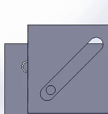
So, here’s the idea: I’m wanting to build the Protector’s Broadsword from Starbound
So first, the easy question: How to set up the “on/off” LEDs? I assume they’d be considered accent LEDs, right? In particular it’s the “off” LED that I’m wondering about. Is there just a setting somewhere that tells the board whether to light it when the blade is or or off, or would it require reprogramming?
Now the more difficult question: Note the transforming hilt. Currently my plan is to use a Proffieboard V2, so would I need to have a separate system in place for driving the motor that transforms the hilt, or is it possible to do everything through the Proffieboard?
So basically, here’s what I’m needing to accomplish: When the saber “ignites”, the motor will run in one direction until the hilt is fully transformed, at which point it will stop. And then when the blade powers down, the motor will run in the opposite direction until the hilt is reset back to its normal position.
I currently have two ways in mind to do this.
Use a standard DC motor with a relay to control its direction, and have a pair of microswitches in the hilt, positioned so that they’ll be pressed by the moving parts of the hilt, one will be pressed when the hilt is in its “normal” state, and the other will be pressed when the hilt is fully transformed, and thus they’ll be able to either cut the power to the motor, or send a stop signal once the motor has run long enough to complete the transformation.
Use a stepper motor to run precisely the number of rotations needed for the transformation and de-transformation, theoretically getting rid of the need for the microswitches to tell it where to stop. (Admittedly I personally am MUCH less familiar with stepper motors, so I’m not entirely sure how well this would work, or whether or not I’d still need microswitches to tell it where to stop.)
So yeah. With this in mind, how hard/possible would it be to program the Proffieboard to be able to handle driving the motor? Would I need to also have a relay to control direction, or would the Proffieboard be able to handle that too?
I’d first look at tiny servo motors that are used in model airplanes, rather than stepper or regular dc motors. They really excel at this kind of application. As for electronics, you might need a driver board, but there are lots of those that work with arduino. Someone else will have a better idea of that though. I’m more of a mechanical guy.
Note in the right-hand column of the Editor page that the last argument, the “color when off”, is Black.
But see how it is not visible in the code in the style box though?
Because it’s a default value, it is omitted from the end of the template.
Replace Black with any COLOR (A COLOR argument can be replaced by a"style" like Blinking, Pulsing, TransitionLoop or whatever.)
This is typically done with accents and Crystal Chamber LEDs all the time.
I like the idea of using servos! That’ll most likely be what I go with, assuming I don’t need anything too bulky to drive them.
Maybe it would be possible to use the extra Data connections on the Proffieboard for driving the servos?
I’ll have to draw out a sketch later, but for now, the picture in my head has a total of 4 servos, which would work as 2 pairs acting together. So basically, on powerup Servos 1 and 2 will move from 0 to 180 while 3 and 4 will move from 180 to 0 (or whatever angle ends up being needed, just saying 180 as an example for now.) and then on powerdown it’ll do the opposite.
So if I’m understanding correctly, I could wire the servo pairs in parallel and so I’d only need to use two of the data connections (let’s say 3 and 4). That is of course assuming the Proffieboard would be compatible with servos. From the little bit of looking and reading around that I’ve done so far, I haven’t yet been able to find anything saying it can or can’t. It may be worth noting though that I plan on using Neopixels for the blade, which I’ve read affects the timer for ALL Data connections.
Servos require a 50Hz PWM input to drive.
Any of the LED pads could do that, but would need a pullup resistor.
Also, the LED pads are normally configured to run at 800Hz to prevent LED flickering.
If I remember correctly, all the DATA pins are tied to the same timer, and while you can use that timer to drive servos, you can’t use it to drive servos AND neopixels.
The V3 proffieboard had an extra timer, which would have solved this problem.
If you need ONE servo output, LED2 is probably the right way to do it. It uses it’s own timer, which is why was able to use it for IR transmission support. I’d have to do some research to see if it’s possible to drive more servos.
If you don’t need any regular LEDs (only neopixels) then the 800Hz timer can be set to 50Hz instead, and all the LED pads can be used with servos (with pullups).
There is also a buch of chips that can drive servoes and can be controlled over I2C. This could let you drive up to 16 servos, but it would take up some space.
Either way you do it, it will require some coding, but I can help with that part.
It’s also not clear how to expose servos inside of profieos, it could be seen as just another blade I suppose, but I’m not sure if that’s the best way to do it.
Ok, so here is the hacky way to control up to 6 servos with a proffieboard:
change this line:
uint32_t carrier = 1702127;
This will change the PWM frequency to ~50 Hz.
50Hz isn’t going to have super-obvious flickering, but when you move the saber around you would definitely notice it if you have LEDs that use SimpleBlade, so I wouldn’t recommend doing this hack if you have standard LEDs to control. If all your LEDs are neopixels, then this won’t be a problem.
Since the PWM signal is now 50Hz, we can use it to control servos, and styles will control the servos. We’ll need to connect a pull-up resistor between each LED pad that will connect to a servo, and 3.3v or BATT+. A wide range of resistors would work. I would probably use a 4.7k, or maybe a 10k resistor.
Note that most servos want a PWM signal between 20% and 80%, also the signal will be inverted because it’s going through a FET. Basically Rgb<205,0,0> could be used to drive the servo to it’s minimum, and Rgb<50,0,0> to the maximum. All the color blending styles can be used to change the servo to something in between.
You, sir, are awesome! I think that’s exactly what I’ll be needing! Thanks!
I will be using a few standard LEDs, but they’ll only be for small things like the indicator lights on the face of the hilt, and maybe a light-up activation button too. A little bit of flicker in those spots shouldn’t be a problem. Heck, if anything it might add some character!
I’m still working on drafting up the hilt pieces and the mechanism for the transforming. I’m sure I could accomplish what I need with only one servo, but in that case, I’d also need to have a lot more gears running throughout the inside of the hilt in order to move everything, so more complexity and more bulk and more stuff that could potentially break, and it would all have to be in the middle of the hilt, which is already going to be crowded. So multiple servos would likely be much easier and more compact, and run more smoothly too.
I’d go with a single servo, and instead of gears, consider wires and pulleys. Gears have backlash, and can get complicated to arrange and expensive to build. You can 3d print gears, but the quality is sketchy using current technology, or you can machine gears, which is super expensive unless you have all the equipment yourself already or can find premade gears somewhere like mcmaster carr. With wires and pulleys, you can avoid all that. If it’s good enough for Tour de France bicycle gear shifting, it’s probably plenty good for a lightsaber prop.
Edit: Oh yeah, almost forgot: Those servos can get rather bulky, especially for the stronger ones that you would want for this application, so it would be beneficial to only use one of them. Also, if you use only one, everything will move synchronously, whereas if you have more than one, each motor will move at a sliiiiiiiightly different rate, and things can get out of sync. This effect is most visible on a first generation Miata or other car with pop up headlights. Simply keep popping them up and down, and watch them get out of phase with each other. if you do it right you can get them going 180 degrees out of phase.
Okay, so how about if I have two servos, one in the left and one in the right parts of the hilt. And with this setup, they both should ALWAYS be performing the same actions at the same time. So with this in mind, would it work to have them BOTH connected to LED2 and be treated like a single servo?
Yeah, the complexity of gears is what first got me thinking of opting for more servos instead of trying to arrange a gearset. That said, I’m going to be needing at least some rack & pinion action for my current idea, but besides that, I’m thinking now that pretty much everywhere else I had been considering using gears could get the same results with much less work and space required by using wheels and belts instead.
The problem I’d have with using only one would be that I would need to put it somewhere in the middle piece, which is already going to be pretty crowded between housing most of the electronics and also having the tang of my blade poking through it. So if I instead use two servos, I can mount them in the side pieces. The size of the servos would be MUCH less of a problem there since there’s going to be plenty of empty space in the upper half of the side pieces.
As for the two being slightly out of sync, I could live with that. It’s not like they’re going to need to do a lot of rapid zig-zagging anyways.
I’ve still got some sketches coming, there’s just a lot to show, and I haven’t had as much distraction-free time to work on them as I’d like. I’ll be sure to share once I have enough done though!
Be careful and make sure you don’t physically link the two motors such that moving one will cause the other to move. If you do that, then you can end up with the two servos fighting each other because they will have slightly different rotations corresponding to a given input value. That said, it is possible to have them both working at the same time and sharing the load, but still not fighting each other. Think of two guys holding a pole horizontally. There is a mark in the middle of the pole that they have to keep centered between them. If they each think “centered” is in a slightly different spot, they will be fighting to get the pole to their version of centered. That’s what you don’t want.
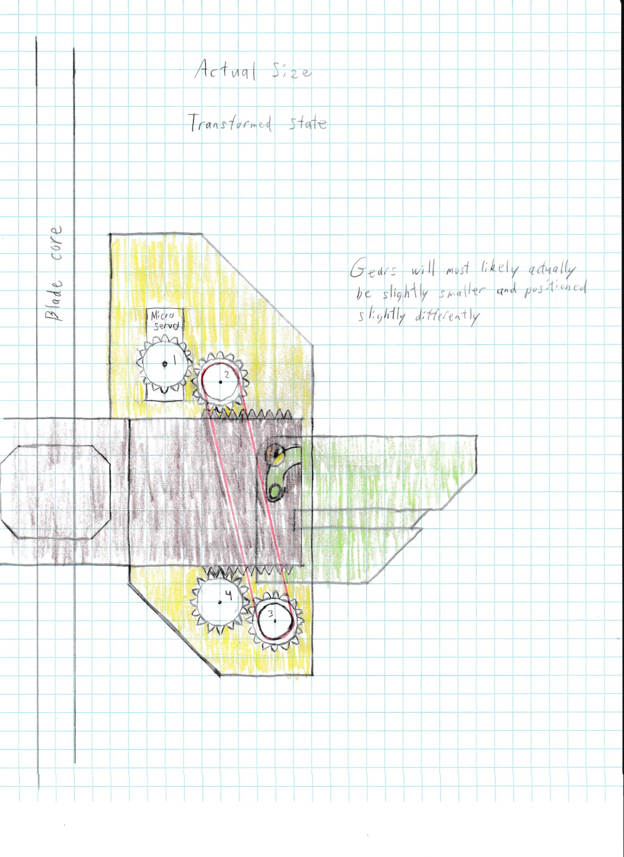
I didn’t draw the servos themselves, but as you can see, there should be plenty of room for them in the upper portions of the side pieces, where they can drive the geared wheels that climb back and forth across the central piece to control the transformation.
The wings will be hinged to the side pieces, most likely using small ball bearings. And the wings will also have a small peg on them. When the side pieces are pulled inwards, the pegs on the wings will glide through a cut-out track in the central piece, and so the peg will be pushed downwards as the side pieces retract inwards, causing the wings to pop out.
Edit: Wow. I’m an idiot. I just noticed a mistake I made with the wheels and belts. But yeah, the concept is the same. there’ll just be a second gear in either the top or bottom to change the spin direction so that the side pieces will walk across the racks. But hey! That’s what concept sketches are for! Makes it easier to visualize ideas than just working all in-the-head.
I’d again recommend avoiding gears. I would use a belt and pulley system instead. saves space, and easier to fix if a tooth breaks. lots of cheap timing pulleys available on amazon too. You might need a single set of 90 degree bevel gears to change the axis of rotation though. That would apply with either a geared system or a belt driven system.
Edit: In looking at your drawing, I think you’ll have to change the cam-slot design. While it would work if the arms were driving the motion, it’s the motors that will be driving it. So you’ll have the situation at the end of travel of the motor trying to push the pin at a perpendicular face. I THINK the same thing can be achieved with just a straight slot, rather than a macaroni noodle.
I’m going to use belts and pulleys where I can, and yes, it most definitely is going to save a lot of space and complexity. But yeah, there’s going to be spots where I just don’t see an easy way to cut out gears entirely. I think in the long run it’ll be easier and work better to just use gears in the few necessary spots instead of trying to figure out a way to go completely gear free. Pretty sure I can find some gears on Amazon too, there’s already a few I’ve been looking at.
Straight slots were my first thought and a couple of my early draft sketches showed them. Here’s why I think they’d be a problem though, and why I believe a macaroni shape is better in this case.
If the slot was going to be at a 45 degree angle like in the gif you posted, then sure, straight would probably be better. But in my case, it’s going to be a steeper 60 degree angle. Therefore, starting at the untransformed state, once it starts moving, the face that would be pushing the cam would be pushing it more inwards towards the hinge than it would be downwards. And since the cam is horizontally in-line with the hinge, it’s going to have more tendency to stand fast, and will likely be prone to locking up once friction in the slot is accounted for. The macaroni shape will solve that issue by guiding the cam with a more gentle curve instead of a hard flat surface at first. And once its past that first bit, being pushed by a near perpendicular face should be less of an issue because the cam will no longer be in-line with the hinge, and so the swinging motion of the wing will bring the cam down as it’s pushed out.
Personally I think you’ll be much better off using as little mechanics as possible. To me that means hoooking up the fold-out parts directly to the servo(s) if at all possible. If not, I would first try using servo linkage rods. These come in lots of different shapes and sizes, but the simplest ones are simply bent pieces of steel wire that fits through the servo horn and connects to whatever is supposed to move. In an airplane, that would be a wing flap, but I don’t think this is all that different.
Gears and gliding peg/slots might work, but seems overly complicated.
Currently I just don’t see a way to connect the servos directly to the wings, at least not without bulking up the build way beyond an acceptable level. And given the different pieces that will be fitting together and sliding through each other, I worry that linkage rods are going to be difficult to manage too.
That said though, it’s still going to be a while before I’ll be ready to print out all the parts and try assembling them, so in the meantime I’ll keep on playing with new ideas and see if I can further optimize it. Maybe I’ll be able to figure out something that cuts out more mechanics.
Heck though, just adding in a belt and pulley system already cut out a lot of the complication I expected would be required. So even if I end up NOT able to further optimize it, I’ve at least got it to a point where I’m pretty confident in my ability to build it.
Still going to go through at least a few more revisions. I’m going to try to get the servo positioned further to the right because of how the sides are going to “hug” the blade, and will limit available space where I currently have the servo positioned (see the picture below) But if the gears I use are going to be smaller than what I drew here, that should definitely be possible.
Since someone’s probably going to ask: the reason the servo isn’t attached to gear #2 is because I want #2 to spin its axle and drive another set of identical gears in the back, so this way the gears will walk along both the front and back edges of the central piece and keep the back and forth gliding more uniform.
McMaster-Carr is a great source for weird parts too. The shipping charges are kinda steep, and the prices are not the best, but they have tons of hard to find stuff in small quantities.
So, shopping for gears is proving to be tougher than expected.
Everything McMaster-Carr has is going to be too large. The smallest gears I’m finding there have 1 inch diameter. For my purposes, I want to try to shoot for 0.5 inch pitch diameter and keep everything nice and compact. Heck, going even smaller than 0.5 inch would be nice, but from what I’m seeing, 0.5 inch would be the most reasonable expectation for minimum size that wouldn’t also have tiny teeth and cheap material that would be prone to stripping.
I’ve found some pretty decent options that meet my diameter requirements at Servo City’s website, and another perk is that they sell gears that fit onto the splines of a servo. However, another problem I’m encountering there is that once I account for the need to stack gears and pulleys on the same shaft in some spots, the options there are going to end up being too thick and will bulk up my sword more than I’d like. Many of my gears will need to spin their axle as well, not just spin in place, so that would necessitate the need for either D-shaped bores, or pinion gears, of which for the compact size I need, I’m only finding the latter at Servo City, and they’re all thicker than I’d like.
BUT I just thought of a possible workaround. I could use these for all of my gears. Of course, as they are, they’d be able to attach to my servos, but as for the ones that would be spinning on shafts instead, I could just 3D print some plugs to insert into the splines, and that would allow me to fit them onto any shaft I like by just adjusting the bore in the 3D model.
Pulley wheels are much easier to design and print than gears too, so where I need pulleys stacked on top of gears, I could simply print the pulleys as part of the plugs. It would all be nice and compact!
Yeah, you can print pulleys all day long no problem. There are even tiny ball bearings available on Amazon for cheap for 1-2mm diameter shafts.
Anyway, it sounds like you’re beginning to appreciate some of the challenges of designing with gears. I would again strongly recommend that you take a step back and see if you can redesign the whole mechanism from scratch using belts and pulleys instead. Small Toothed pulley wheels are readily available as are toothed timing belts, both in make-your-own form as well as premade. They tend to be much easier to source, cheaper, and for simple, low speed, limited travel mechanisms like this, can remove a ton of headache. Might not be the right choice, but I bet it will be, and at the very least by going through the exercise you will likely think of some different ways to do stuff in a fully geared version as well, if that’s the way you end up going.