An idea and some newbie questions (motorized transforming hilt)

And I think that both gears and belts are overkill.
A single link-rod can solve this entire problem, without moving the servo from where it is in the drawing.

It just needs to go from the 6-o-clock position on gear 1 (or a servo horn), to an equivialent position on the green part. (meaning same distance down from the fulcrum)

Link-rods can be made out of anything, as long as it’s stiff enough.
If precision is required, maybe design it as a PCB and order it from oshpark?

Using more than one link-rod can reduce slack in the mechanism if desired.

I mean, how can it get any simpler than that?

Only issue I see with using linkages is that the horns take up a bit of room… I suppose with a powerful enough servo the horn length can be reduced. Depends how heavy everything is, and how much travel is needed.

Assuming the length of the horn, and the distance from the fulcrum on the other side is the same, the amount of force the servo has to apply is the same. (Not counting friction and other minor factors.) However, the shorter the horn, the higher the force will be on the linkage, and any slop in the mechanism will be magnified.

Another way to stiffen up the mechanism would be to use a dual-axis servo. (Axis sticks out the bottom, and there is another horn on the other side.) That way you can have linkages on both sides, which reduces lateral movement significantly. These servos are popular in robotics, but I don’t know if they make them small enough for this application.

Huh, that’s not a bad idea! I’ll try browsing around and see if I can find one that fits my needs.
So far, from the little bit of searching I’ve done, it’s looking like most dual-axis servos are going to require more voltage than an 18650 battery can provide though, so that could end up being a problem. I’d like to avoid using multiple batteries if at all possible.
Edit: I completely forgot about the 5V output on the proffieboard. Maybe that could work!

Maybe if single axis servos end up being my only option, an alternative to try would be putting horns on the axle with gear #2 and accomplishing the same idea that way. If that works, it would reduce the number of gears needed to only 2 total on each side: only the servo gear, and the gear connecting it to the axle driving the horns.
It’s worth a shot!

Another edit: Another problem I’m running into is that it looks like all the dual-axis servos I’m finding at a compact enough size are only actually splined on one end, and rely on the use of a U bracket to keep motion uniform on both ends.
Just as I was about to give up on the idea though, a possible way to make it work came to me! It’s an idea that could alternatively use a VERY simple gear system instead of horns too. I’m about to have to go to work now, but if I have time afterwards, I’ll try sketching it out tonight.

Been a while since I’ve given an update on this project.
But first a quick question, just to be sure. I read that the 5V output on the proffieboard is normally only on when sound is playing. There may be some rare cases where I need to power the servos without sound playing. The main one would be on startup: If the power had previously been cut while the hilt was in a transformed state, then the servos would need power to reset back to the standby position.) So would the 5V pad still be suitable for that?

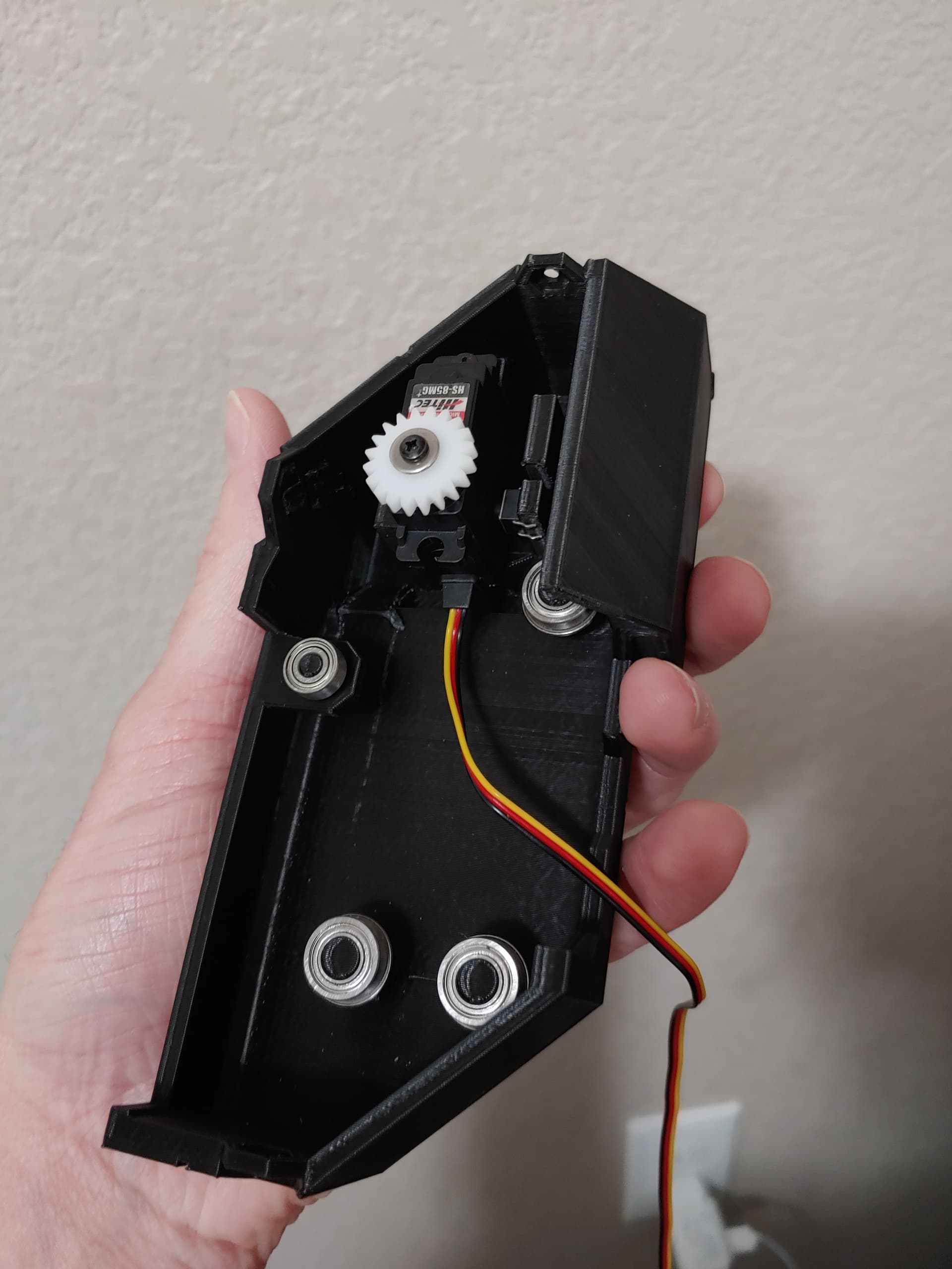
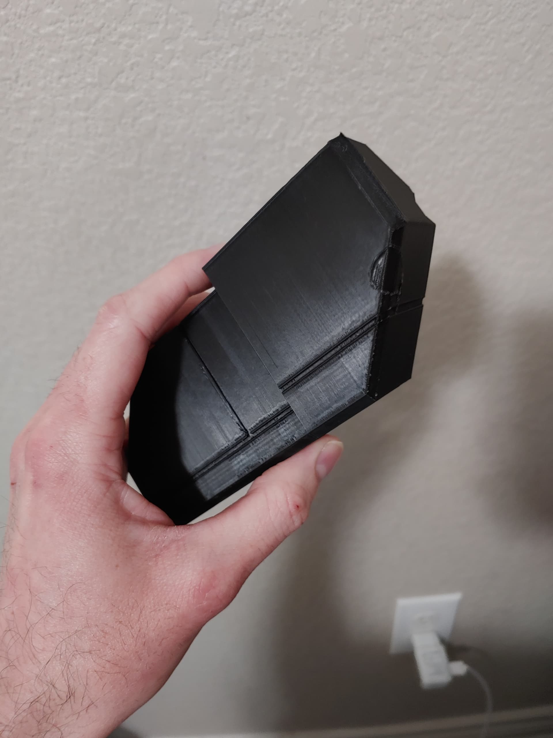
Anyways, on to the update to this project. This will probably be the last sketch I post, because at this point I think it’s ready for 3D modeling! That just might take a little while because I unfortunately no longer have access to the software I’m most familiar with, so I’ll need a little bit of time to relearn with different software. That’s going well so far though. I’ve been working through some online video courses and progressing pretty quickly.

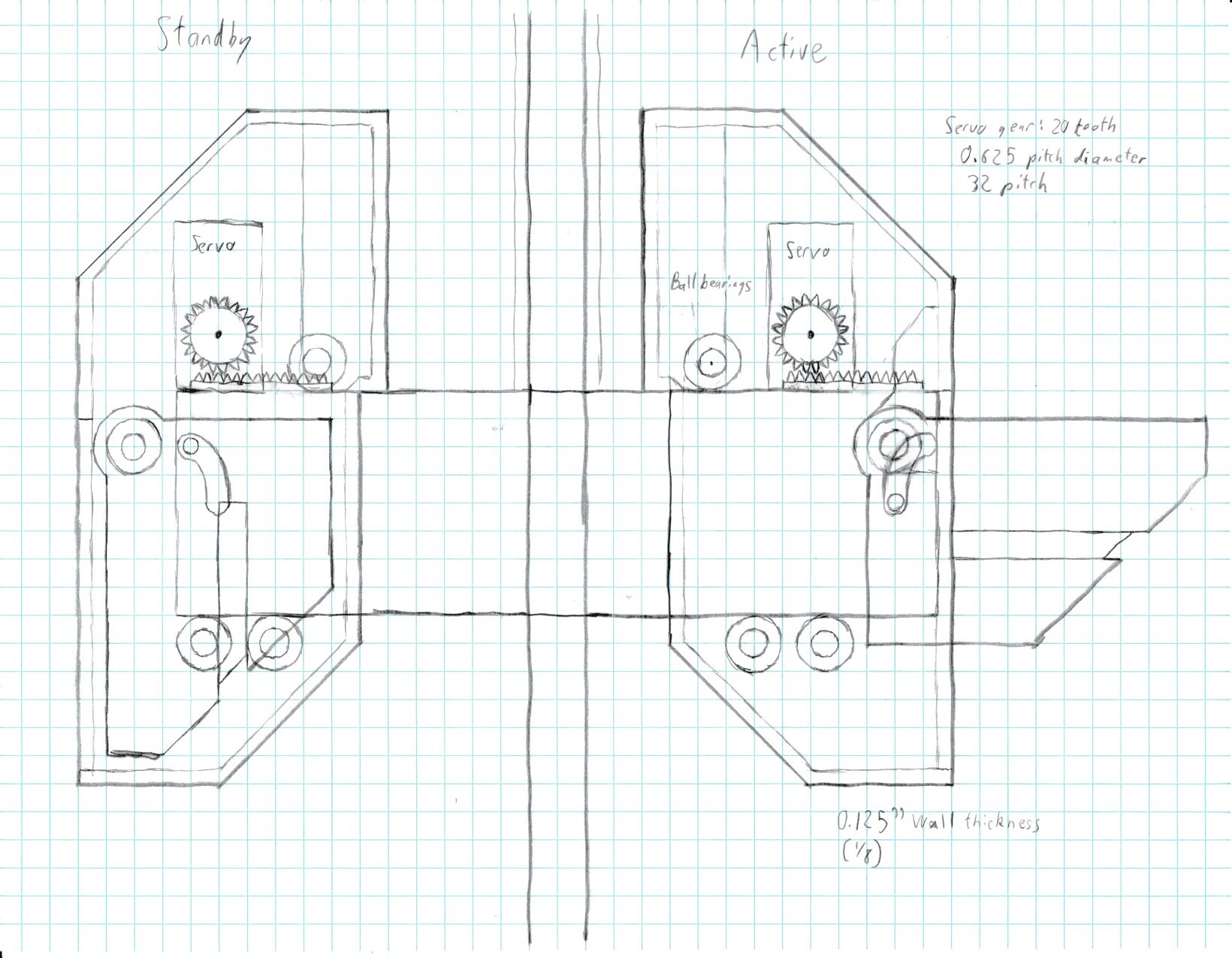
So as for details, the main reason I had originally wanted to surround the centerpiece with gears was to counteract friction and reduce wiggling and lateral movement by having something to “hug” and apply force on both sides. Well, I don’t know how I didn’t think of this sooner, but the need for all that can be gotten rid of simply by having it roll along ball bearings instead of just sliding through!

I sketched it out with gears, but this could also use horns too. In the active/transformed state, the horn would be pointing straight down and have a pin going into a track in the centerpiece. In standby/untransformed state, the horn will be pushing the centerpiece outwards (or more accurately, pushing itself and the side piece housing it away from the center)
I’m most likely going to stick with a gear and rack driving system in the end though since it’ll keep the forces closer to the servo and therefore reduce the amount of torque needed.

I’m also going to tweak the cam-slot system for the wings a bit as well.
Hilt
After looking at it as an animation, I think Celemourn was right, particularly when the side pieces are spreading out and wings are retracting. I can see the near-perpendicular face of the slot possibly causing problems there. Though at the same time, I think the curved shape would still work best when the sides compress and the wings pop out.
So I’m going to try using both at once! The innermost wall of the slot will keep the curve, while the outermost wall will be mostly straight, save for just the endpoints which will have a slight edge that the cam will “fall” into to hold it in place until the mechanism moves again. Also, instead of a simple peg, I’ll use a tiny ball bearing. With this setup, the wing will ride along the curved wall when transitioning from standby to active, and will instead ride the straight wall when transitioning back.

Some 3D images of the hilt are coming soon! And I should have all the materials I need for getting started with building a blade by the end of the weekend! I’ll be starting with a coated foam blade, and maybe will try a nylon or PC blade at a later date.

2 Likes

Good call on using a tiny ball bearing instead of just a pin.

Okay, so if I’m understanding everything correctly, the “blade” for the servos should look something like this. Correct me if I’m wrong.
WS281XBladePtr<1, bladePowerPin2, Color8::RBG, bladePowerPin1, DefaultPinClass, 50000, 300, 394, 894>
Admittedly I have no idea what the pin-class, reset_us, t1h, and t0h should be, so I’m just sticking with defaults. Not sure if the difference from the normal frequency will affect those last three or not.

As for hooking everything up, it’s looking like I’m probably going to require 5V power for the servos, so if I’m understanding this correctly, the positive side of the servos should connect to the 5V pin on the board, and the negative side should connect to LED1, right? Also, I read that the 5V pin is normally only on when sound is playing. So what do I need to do to ensure that it’s on when I need it to be? I don’t plan on using the 5V pin for anything else, so it’ll only need to be on during transformations.

I sure picked one heck of a first project! :rofl: But that just means that if I survive this burn-in test, everything else I do in the future will be easy! :laughing:

Ok, I’m correcting you, because this is wrong.
This blade would put an neopixel signal the LED2 pad. Neopixel signals are 800kHz signals, that uses long and short “high” signals to transmit ones and zeroes. It’s not what you want.

This would be better:
SimpleBladePtr<CH1LED, NoLed, NoLed, NoLed, bladePowerPin2, -1, -1, -1>()

It would produce a PWM signal, which is what a servo needs, but unfortunately it will do so at about 800Hz, rather than the 50Hz that the servo wants.

The easy way to change it to 50Hz is to change this line:

If you make it:

   uint32_t carrier = 50 * 32768;

Then the output will be very close to 50Hz. Note that this will change it for all simpleblades, if you want to change it only for LED2, please let me know and I can show you how to do that.

Most servos will happily work with lower voltages. I would try hooking up the servo to the battery + and - and see if that works first.

The good news is that if you do need the 5v pad, it should be active anytime a blade is active. (To prevent the FETs from running in a half-on state and heating up.)

Little bitty update on the project.
3D modeling is taking way longer than I expected, mainly because my day job and preparing for the holidays is leaving me with way less free time lately (and I’ll be honest, getting distracted by Pokemon Violet too :laughing:). There’s not really enough to show yet, but I’m doing just a little bit every day, so slowly but surely making progress.

The main thing I wanted to mention though was I just got a new idea! Regarding the safety/abort button I talked about here. Rather than mounting buttons on the surface of the moving parts, what if I instead mounted the servos so they’d have a little bit of wiggle room, but would be held in their correct place by something like a small spring or a piece of squishy material, and then I mounted NC microswitches up right next to the servos so that the button would stay pressed and keep them open?
The way this would work is if the transforming parts encounter an obstruction, as the servo continues trying to spin, it would wiggle itself slightly out of place, just enough to release the microswitch and trigger a button pressed event to abort the transformation.
Doing it this way would have two perks over my old idea: It wouldn’t require visible buttons or levers on the surface of the moving pieces, and more importantly it would be able to respond to ANY obstruction, not just obstructions that make contact with a button.

That is an interesting idea, but I wonder it might be difficult to implement well? Getting the “squishiness” just right seems like it could be a challenge.

However, it does spark a host of ideas for other ways to do something similar. Not sure if those ideas are useful at all, but I thought I’d share anyways. You could…

  • Use a pressure sensor instead of a switch.
  • Measure how much current the servo is drawing and shut down if it’s drawing too much.
  • Use a servo with positional feedback, and shut down if the servo isn’t moving fast enough.
  • Use a bendable linkage between the servo and the moving parts, and detect the bending.
  • Not do any of these things and just make sure that the servo you choose can handle it anyways.

The current draw idea may be as simple as putting a resistor in series with the servo. If the current draw is small, the resistor won’t do much and the servo will work normally. But if the servo is trying to work hard, the current draw will go up, and more voltage will be lost in the resistor, causing the servo to loose power. Essentially it will make the servo weaker. Measuring the voltage over the resistor would then let you detect when the servo is trying to work hard so that you can shut it down.

Interesting ideas! I looked into pressure sensors, and the ones I found look like they’d need more wires than I’d like to have. Space is going to be pretty tight in a few spots, and this is one of them due to needing to keep the wires out of the way of the wings, so I want to minimize the number of wires needed.
That did give me another idea though. I had forgotten that I had a few of these on hand…


The idea would be similar to the microswitch idea, but it would press the button instead of releasing the switch. It looks like these buttons could potentially make a spring less necessary too since they require a fair amount of pressure to click. I tested the idea by holding one up against some battery boxes and pushing them across my desk. I had to put a little bit of oomph into it to get the button to click.

I like the current draw idea too! That would also help with reducing the number of wires needed. I’m not sure how to program the board to check voltage though, so I’d need some help there if I go with this idea. Also, how many ohms would you recommend? I would assume it would need to be fairly low to not weaken the servos too much.

The way to measure current is to add a (small) resistor, and then measure the voltage across it. Proffieboards only have pin that can do analogRead, which is Data4 if I remember correctly.

If a slightly larger resistor is used, it will reduce the current and weaken the servo, if that’s what you want.

Been a while since I’ve posted an update!
I’m still working on modeling the chassis and handle, but the transforming pieces are just about finished now. I’ve been making a few test prints with relatively cheaper material to see how well the components all fit inside, and to figure out a good orientation and support system that minimizes blemishes on the outside surfaces while still keeping everything supported in a way that’s easily removable. I’ve got everything fitting in pretty awesomely, but the problem I’m dealing with now is zigzag style supports fusing too firmly in a few spots, and tree supports putting branches in undesired places and blemishing the surface (as shown in the second picture).
I’d prefer to not have to sand any of the outside surfaces if it’s not absolutely unavoidable. Because, well, I really like the lined look of printed parts, and also because I’ll be using a silk filament for the final product, and won’t be painting it. A past attempt to sand off blemishes ended up affecting the look too much.


The safety button idea for the servos looks like it’s going to work great too! (Notice the small button that’s mounted to the right of the servo in the first picture) The mechanism is stiff enough that I’m probably not going to need to pad the side of the servo like I thought I would, but there’s still a little wall there just in case I end up needing to slip a piece of rubber or foam in to make the safety mechanism less sensitive.

1 Like

You can experiment with different infill algorithms for the first layer.
Some look much nicer than lines IMHO. :slight_smile:

I believe I’ve finally perfected the print for the side pieces, but going to do one more test print to make sure.
So the problem I was having before was branches of the support tree poking through the model in order to reach something small like a screw hole, and then said supports leaving ugly blemishes on the finished piece. So I got around that by working some DIY supports into the model itself to cover those small problematic spots.
Now the print preview looks like this! Supports are only where needed and making no contact with any flat surfaces!


There may potentially be some ugliness on the inside, but so long as the hardware still fits, I don’t care about blemishes in places that won’t be visible anyways once everything’s assembled. :smiley:

1 Like