Hey y’all,
I’m trying my hand at building a lightsaber after my last attempt failed. My greatest difficulty was wiring to the BATT+ pin on the board, as my wiring diagram has me connecting three things to one tiny pin (battery+, recharge port, and the PCB+ wire. I am just wondering how other people worked around this to connect these three wires to one pin. Do I just need to “git gud” at soldering and have three individual 24-gauge wires coming out from that pin?
I’m considering wiring the Battery to the Recharge port, then a second wire from the Recharge port to the board, then finally a third wire from the PCB to the battery. Thoughts?
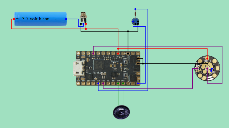
I always use the PCB as a distribution hub, something like this if you have room for the wiring.
1 Like
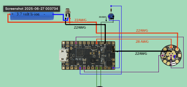
How are you connecting the battery and the recharge port? Are you cutting the silicone sheath and splicing it to the main wire, like halfway up the length? I’ve only got 24 and 30 gauge wire handy, do you think it will make a significant difference if i use 24 for where you suggest 22 and 28?
Additionally, I am considering purchasing some JST connectors to try and make assembly easier for myself later on. Thoughts? Is there anything I should watch out for?
Having connectors so that things can be disassembled easily is really nice. But beware that wires and connectors take a fair amount of space. Make sure to get the smallest connectors you can find, and don’t use them for the wires that carry power to the blade. (You can use connectors to carry power to the blade, but you’ll want different connectors for that.)
More info here: The Connector Contingency
1 Like
Trying to calculate which resistor type I ought to buy, should I take into consideration the resistance that 30-gauge wire would provide? If I am wiring my activation switch as shown above with 30 gauge, does it even need a resistor since it’s such a small wire anyway?
The resistance of the wire will be very small, 338.496 \Omega per km…
So if your wire is 20cm, we get 338.496 * 0.2 / 1000 = 0.0677 \Omega.
Basically, you can ignore the resistance of the wire.
Normally what you want to do is to use this formula: R = \frac{V_{in} - V_{led}}{I_{led}}
V_{in} is 4.2, for a fully charged battery.
V_{led} is the forward current of the LED, which is typcally 2.1 to 3.4 volts, depending on the LED.
I_{led} is the current the LED should get, which is usually 0.02 (20mA).
So, if the LED wants 2.1 volts, you calculate (4.2 - 2.1)/0.02 = 105 \Omega. Resistors with higer values than that will also be safe, but will reduce the brightness to some degree or another.
We can also calculate how many watts we need for the resistor, using the formula W = ( V_{in} - V_{led} ) * I. In our example above this is (4.2 - 2.1) * 0.02 = 0.042 W. This is small enough that the wattage rating of the resistor basically doesn’t matter.
2 Likes
you are my hero.
Yeah, science!