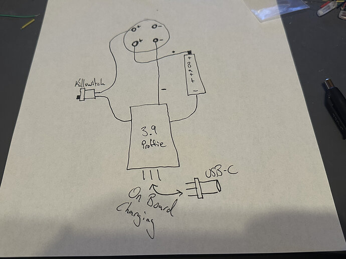
Hey all! Wanted to see if this diagram would work for 3.9 proffie. I typically run a single wire from rotary pcb Positive, split to kill switch and battery positive, then Killswitch to board. I wanted to ask:
-
Does it work if I use a wire from Rotary Pcb Positive to Killswitch, and a wire from another Positive pad on the same (trace? Channel?) on the rotary pcb to Battery positive?
-
Does the diagram create any quirks with on board charging via USB-C?
-
Would it create any quirks when chassis is removed or would it still act as if both positive wires are technically one?
Thanks!
