I have a bunch of parts laying around. Enough to do these installs. I am an endless planner, so I would like any feedback about these installs… They are all pretty straight forward, imo.
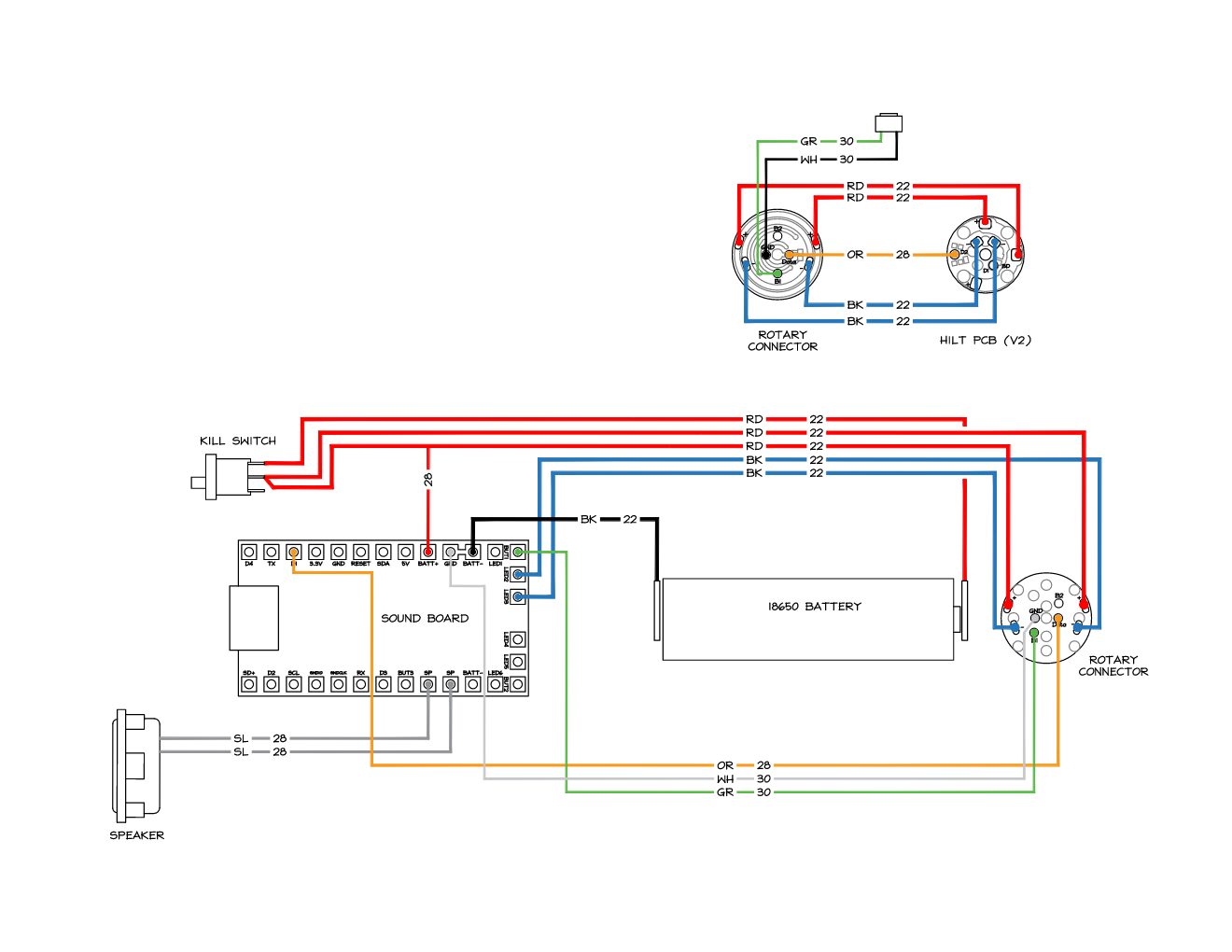
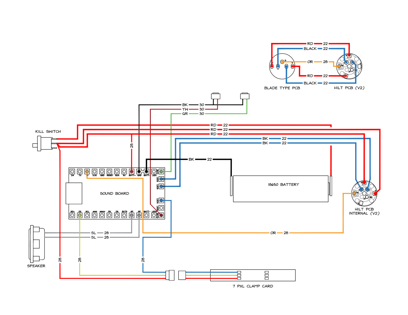
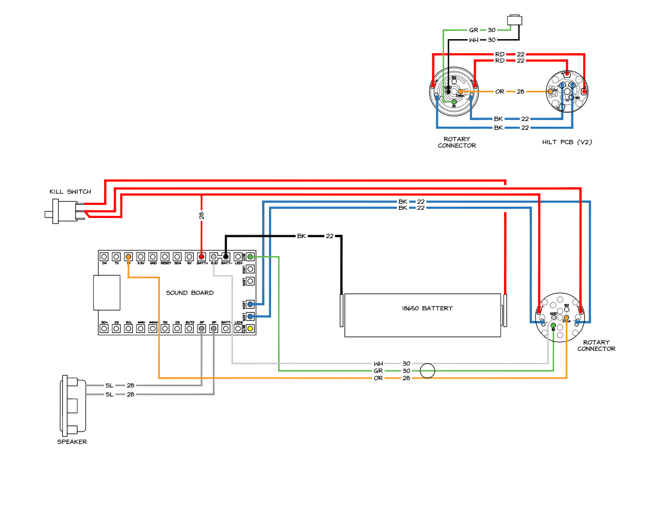
All are wired in “V2” configuration mirroring the hilt pcb and blade.
I have been working on the chassis files in fusion, With the exception of the scavenger, I have an eco chassis for that. I also have a blaster install planned, but I will start a new topic for that, as it differs from a saber.
The switches attached to the rotary connector are cool. Which connector is that, if you don’t mind me asking?
Otherwise, without seeing your configs there’s no way to be absolutely certain. But they read well and seem fine as long as the code matches up Data runs look good. Power is fine. Just not sure about the swtiches attached to the rotary connector, as that’s new to me.
You don’t need 2x 22awg wires for the blade + & -, one for each is sufficient and just bridge the LED 2/3 pad. You can also use 30awg for speakers and data lines.