Hi Everyone,
Would you mind take a look at my wiring diagram if it is good like this? First time tinkering with a Proffieboard (used CFX before) and I am not really an expert with circuits.
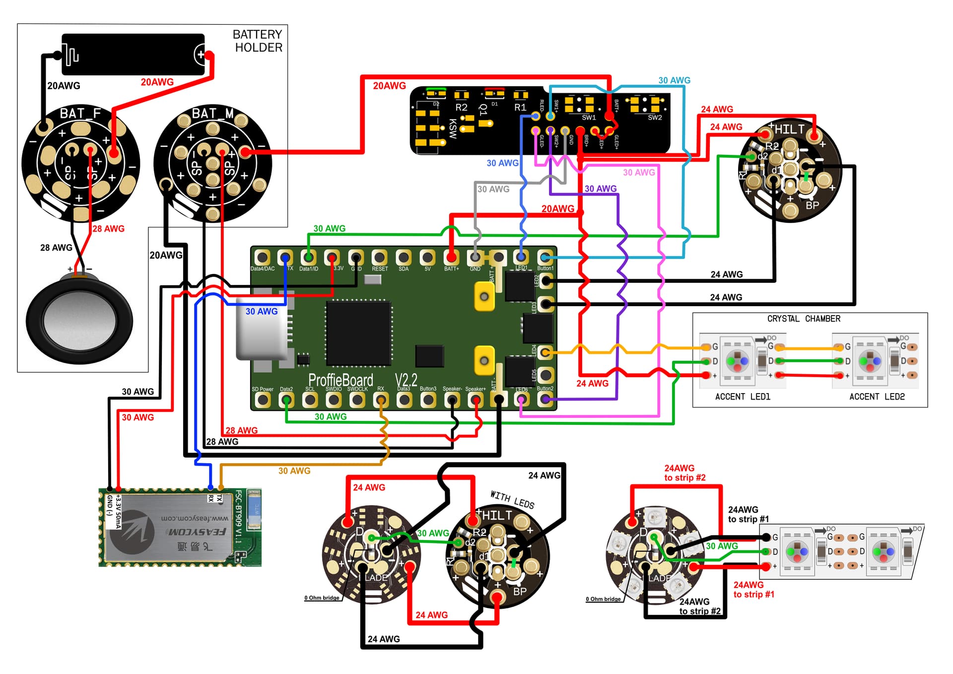
Saber is a 7Chambers MoM Luke that is why there is the helper board (it is a v2) also I am using a removable battery chassis setup, the battery holder will have the Shtok Battery connectors, then the crystal chamber will connect with the Shtok NPXL connectors, at the end the blade with also the NPXL connectors.
Bluetooth module is optional I don’t think I have space for it, but I wanted to do a whole wiring diagram for later use as well.
Let me know if there is anything to change!
Thank you!
You don’t need more than 26 gauge on the board positive. And I’ve found the 22AWG much easier to solder to the proffie since they can go through the holes (I’ve never tried 20AWG). Personally, I use dual 22 on the path between batteries and main blade, but dual 24 what the manual says. I guess that unless you use a maximum brightness pure white 130+ pixel blade, dual 24AWG should be fine. But to the board’s positive, even 24AWG is overkill. The board’s negative should be dual 24AWG, or single 22+. Please note you have two Negative pads, if you want to use thinner cables.
1 Like
Copy that, thank you!
Other than the wire gauges everything else is fine? I connected everything as it should be?
Well, for the Bluetooth, they recomend to solder a 47-100 uF 6.3-10V ceramic SMD 0603 or 0805 capacitor between +3.3V and GND, because the 909 has a spike of consumption at start up that might rreboot the board. Also, if you don’t put an on/off switch, I would recomend that you connect the BT GND (negative, actually) to LED 5 and so you can turn it off automatically with #define IDLE_OFF_TIME 60 * 10 * 1000. I think all this is in page 19 of the V7 edition of the Proffie V2.2 manual (the second page dedicated to BT).
1 Like
I don’t think I will have enough space for the BT module but I will look into it! Thanks for the info!
I will print this and star to put it together tomorrow. Hopefully I will not run into any problems 
one 22AWG is fine for the battery. And then you can use one 22AWG for the pixel PCB as well. Cleans up a mess of wires.
So 22AWG for both negative and positive for battery holder to BAT F, then from BAT M also 22 AWG negative to the Proffieboard and 22AWG positive to the helper board, then 22AWG from helper board to Proffieboard BATT+. Also 1 22 AWG positive and one 22AWG negative (LED2?) the the NPXL PCB? All the way up to the blade?
Helper Board to Proffie 26/27AWG is fine.
I am planning to do it with 32AWG for the switches and the leds.
If you mean the crystal chamber, if you only have two elements, you can do it. Worst case scenario current for two WS2812B pixels is 84mA (RGB). And 32AWG wire is rated for 91mA. As long as you don’t make the chamber full white, you should be fine.