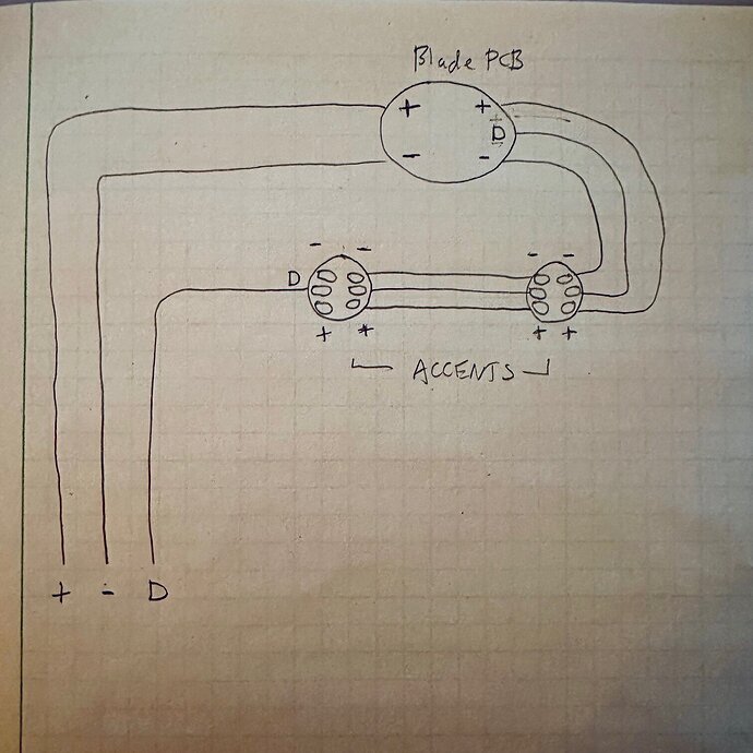
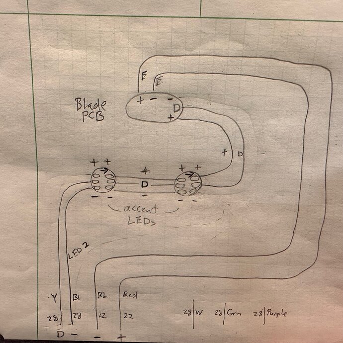
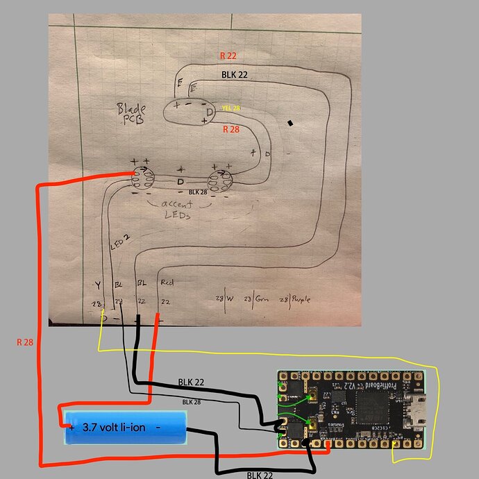
You have 1 data line to the PCB (data 1 from the Proffieboard).
Hilt side blade PCBs are typically wired to either be parallel with the main blade, or dedicated as their own blade (no data out option from the last 16th pixel)
If in parallel with the main blade, you would not count the 16 as separate SubBlade, since they are lumped together with the main. That means that whatever shows on the first 16 pixels of your main blade will be mirrored on the PCB.
The other wiring possibility is if they take their own data, are their own 16 pixel blade, and the data ends there.
I’ve not seen one wired where the PCB takes the data through it’s 16 pixels first, then continues from there on to the main blade in series.
Does that make sense so far?
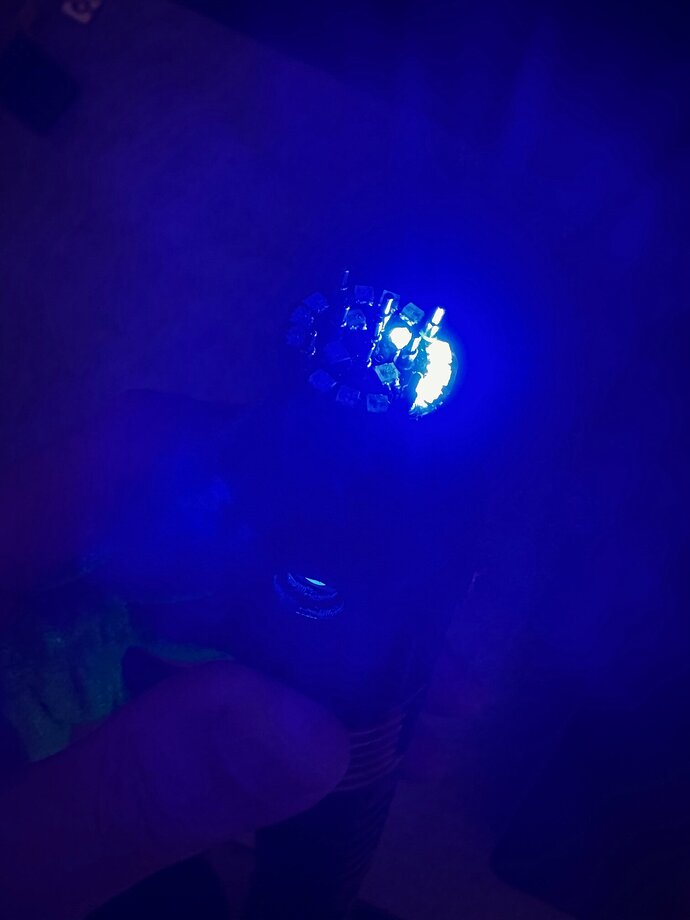
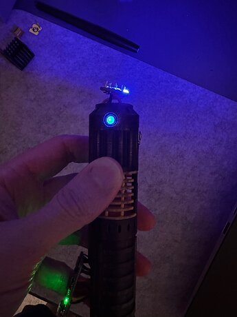
When you said starting simple, you were on the right track. The first thing I would suggest is making sure all of your pixels actually light. This would mean just make one blade, with one standard blade definition with the total number of pixels on your chain and set it to a single color, or better yet use Rainbow to test that they all light and that each one can do R,G, and B.
So if your main blade is indeed in parallel with the PCB, then you have 1 accent, 1 accent, 16 PCB pixels. That’s 18 total, so to test you’d do:
BladeConfig blades[] = {
 { 0,
  WS281XBladePtr<18, bladePin, Color8::GRB, PowerPINS<bladePowerPin2, bladePowerPin3,bladePowerPin5> >(),
  CONFIGARRAY(presets) },
};
That’s without the main blade in (so you can see the PCB).
It’s also a little weird because you split the power to a different LED pad, so we need to include them all since the data line is the same (I think, I never did that before).
Why not just wire the accents to the same LED 2&3 pads the Proffieboard a with the main blade and PCB?
Anyway, once you know they all work (which also means you’re wiring is good) ,
then you can split it into SubBlades and add in the main blade, which would be:
accent = 1 pixel
accent = 1 pixel
main blade = 132 (the PCB 16 pixels is already included in here because it’s wired in parallel)
  SubBlade (2, 133, WS281XBladePtr<134, blade2Pin, Color8::GRB, PowerPINS<bladePowerPin2, bladePowerPin3, bladePowerPin5> >() ), // Main blade and PCB
  SubBlade (1, 1, NULL),  // accent #2
  SubBlade (0, 0, NULL),  // accent #1
Assuming you meant in series like your diagram.
