Hello The Crucible community,
I am trying to assemble my first lightsaber build. I have a Proffieboard V3.9 and a cram-fu chassi (OLED & BT).
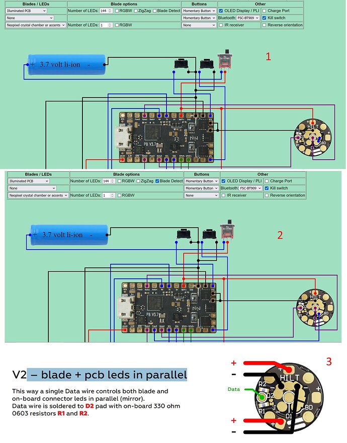
My NPXL connector came with R1 and R2 pre-soldered. I would prefer not to have to de-solder any of them (my de-soldering experience is inexistent with such a tiny component) so I guess I need to wire it as “V2 – blade + pcb leds in parallel”.
I am confused as to which wiring diagram to follow 1, 2 or 3 (attached) ? Diagram 3 (from the NPXL manual has both R1 & R2 but diagram 1 & 2 from hubbe.net only have R2 present (difference between 1 & 2 is with or without blade detect - I would prefer to do with blade detect).
Thank you for any insight you can share.
You could just clip it right in the middle with a clean pair of sidecutters, tip down (a little carefully). Then add a little solder to the tip of your iron and just move the resistor halves away. The configuration generator allows you to set up an illuminated pcb as a separate blade so the a lovely progressive ring of light appears on those little leds. Looks cool. You won’t get that if the data is in parallel.
Otherwise, the D2 pad (normal data) on the PCB gets the data line. That won’t be in the configuration generator. Just select a normal blade in the dropdown to get the right blade array.
Not sure about blade detect, haven’t tried it.
1 Like
Thank you LyleStyle,
Ok so R1 has to go. I hope I do not mess it up !
So that will set me up for NPXL “V4 – blade + pcb leds independent” with data1 & data2 wired to the Proffieboard as per diagram 1 or 2. I am guessing D2 is for controlling the NPXL connector Leds and D1 is for the blade ?
Now I need to decide if I go blade detect or not. ? What are the pros/cons of blade detect or not ?
Thank you.
That sounds right.
And Blade Detect rulez lol.
At minimum for having the option to play a sound with that action.
There’s no harm in wiring up for it even if you decide not to use it, other than taking up some space inside with the wire.
1 Like
Thanks NoSloppy,
I managed to remove R1 just with a bit of solder on the tip of my soldering iron. It is so tiny I wasn’t sure I got it of. I hope I never have to put it back on. And it is now wired for blade detect.
1 Like
Ha, yeah. Well done saving it! If I had to, I’d use a little solder braid to clean the pads. Then use a little tape to do the ‘tuck it into bed’ technique. Half the little guy goes under the tape. Secure in place. Solder the exposed side. Remove tape. Solder other side.
1 Like
