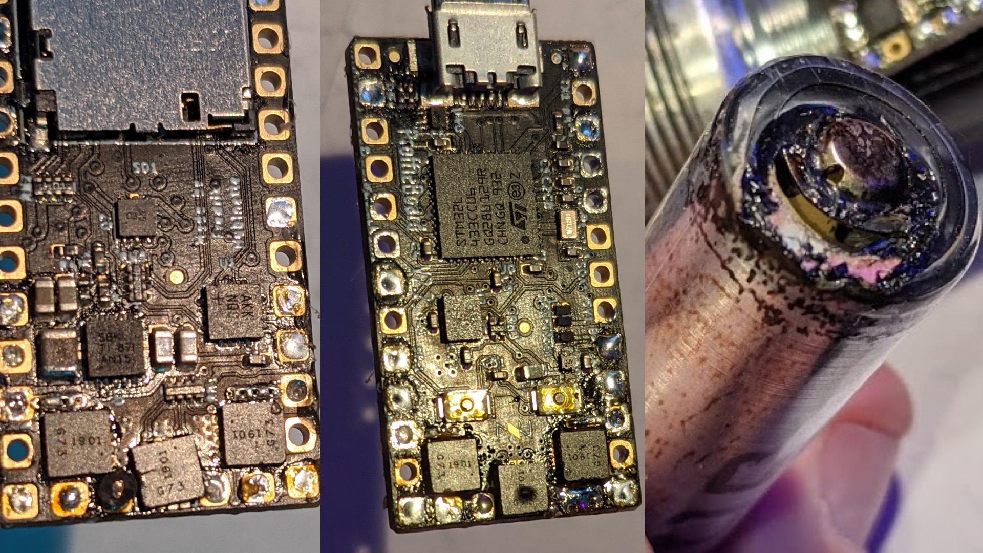
So I just released some magic smoke from a Proffieboard.
It’s the first time I’ve ever done so, and it was by inserting the battery backwards in the dark. The visual carnage was FET 3 had a raised bump, and FET 4 heated up enough to actually slide off the SMD pads and is crooked now. Oddly, the spring battery terminal seems to be the worst damage along with a melted button top on the battery’s positive end, yet the battery protection circuit didn’t pop.
I am wary to clean it up and re-use, although it responds normally via USB with nothing attached to it.
The question is, aren’t diodes in place to prevent backflow of current in this situation? I must misunderstand what protection is in place as of the 2.2 boards.
The reverse polarity protection on the board protects everything except the FETs and the blade.
The reason for this is that the FETs carry a lot of power, so reverse polarity protection would be very bulky. However, for the FETs to carry current backwards, the current also has to go through your blade. Dmitry pointed out a while ago that WS2813 based blades have reverse polarity protection in them, but most other neopixels do not. Of course, old-fashioned LEDs have reverse polarity protection since they are diodes.
The V3 throws another caveat into the mix: The reverse polarity protection won’t really work while charging. So if you plug in your battery backwards and try to charge it, you end up with a very efficient battery drainer…
I must admit that I’m surprised that the protection circuit didn’t kick in though.
I suppose 15A is quote enough to melt things.
Btw, there should be nothing wrong with re-using the board as long as you test if the FETs work as expected first. You may need to re-seat or replace them though.
2 Likes
So maybe I’m not thinking it through enough, but why would this melt stuff though? If it’s BATT±>Neopixels, and pixels->FET->through board ->BATT-, where’s there current flowing that’s different than correct polarity? I have APA105 strips, which are SK6812/WS2812. They didn’t get zapped. This is a dumb query isn’t it.
When the current is going the right way, the LEDs in the neopixels are actually limiting the current. Even when displaying white, each neopixel will draw a maximum of 60mA according to the data sheet.
When the current is going the wrong way, the pixels are probably working more like shorts, thus pulling a lot more current. This would likely cause the blade to heat up, but since there are a lot of neopixels in there and the heat is spread out, other things will melt first.
2 Likes
I didn’t know about RP protection being built into 2813s…have to look into that. I’m a fan of SKs, personally.
Acting as a short would make perfect sense. Seen some impressive cookery due to shorts, and since you’re not getting natural current limiting via each pixel…you basically have a heatsink down the blade. Board doesn’t have that luxury.
Just a thought, and I am by no means an expert but would a nice beefy schottky diode placed at the + on the battery holder work as a rudimentary reverse polarity protection for the whole system?
It would work, but a FET would actually be better. A FET placed in the correct will have a much lower resistance than a diode. Lower resitance means less heat and less “beefyness”.
1 Like
WS2813 led strips have a protection but are less bright than SK6812 (that latest KR V2 pixelsticks are using).
Shottky diodes are simple, but not efficient, because they drop the voltage by 0.5V or even more, which will result in a lower blade brightness, which we don’t want…
1 Like
I agree totally, seems like it would be worthwhile to have some sort of protection just in case of any mishaps.
At least it wouldn’t end in tears that way.
As prof suggested would a fett be better?
I’m just trying to keep it simple but not have too many drawbacks.
Like you said, we spend good money to get a bright powerful blade, and then restrict its power… just wouldn’t make sense.
So the hunt continues to see if this is something achievable.
A fet would absolutely work, but a FET that can protect the whole saber would have to be fairly big.
I’ve often thought about using a pFET like this one:
Interestingly, the drain is connected to the heat sink on the FET, and in a reverse polarity circuit, the drain would be connected to the plus end of the battery. (See here: https://www.ti.com/lit/an/slva139/slva139.pdf)
So in theory, you could build a 3d-print a battery holder where the back of the FET touches the battery positive terminal directly. Since we only need reverse polarity protection if there is a battery holder, that might make sense anyways.
I’m game for anything that could work.
I’m always happy to try something out to see how it stacks up.
I’m building on a relatively small budget and would hate it if I made a simple yet destructive booboo.
You could test the reverse polarity with a resistor or something before you hook it up to a real saber.
Yes that would be a good idea, would make it easy to get test results too
1 Like