Using a different USB-C connector

Hi! Thanks in advance for any help. I can’t easily procure the female 14 pin USB-C female to USB-A male module. What I did, is I bought a few female USB-C to male USB-A adapters and cut the plastic off. I have the pictures of the pcb. It is damaged, but I have more to open and now I know how to open it.

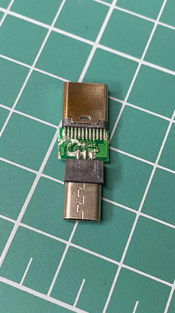
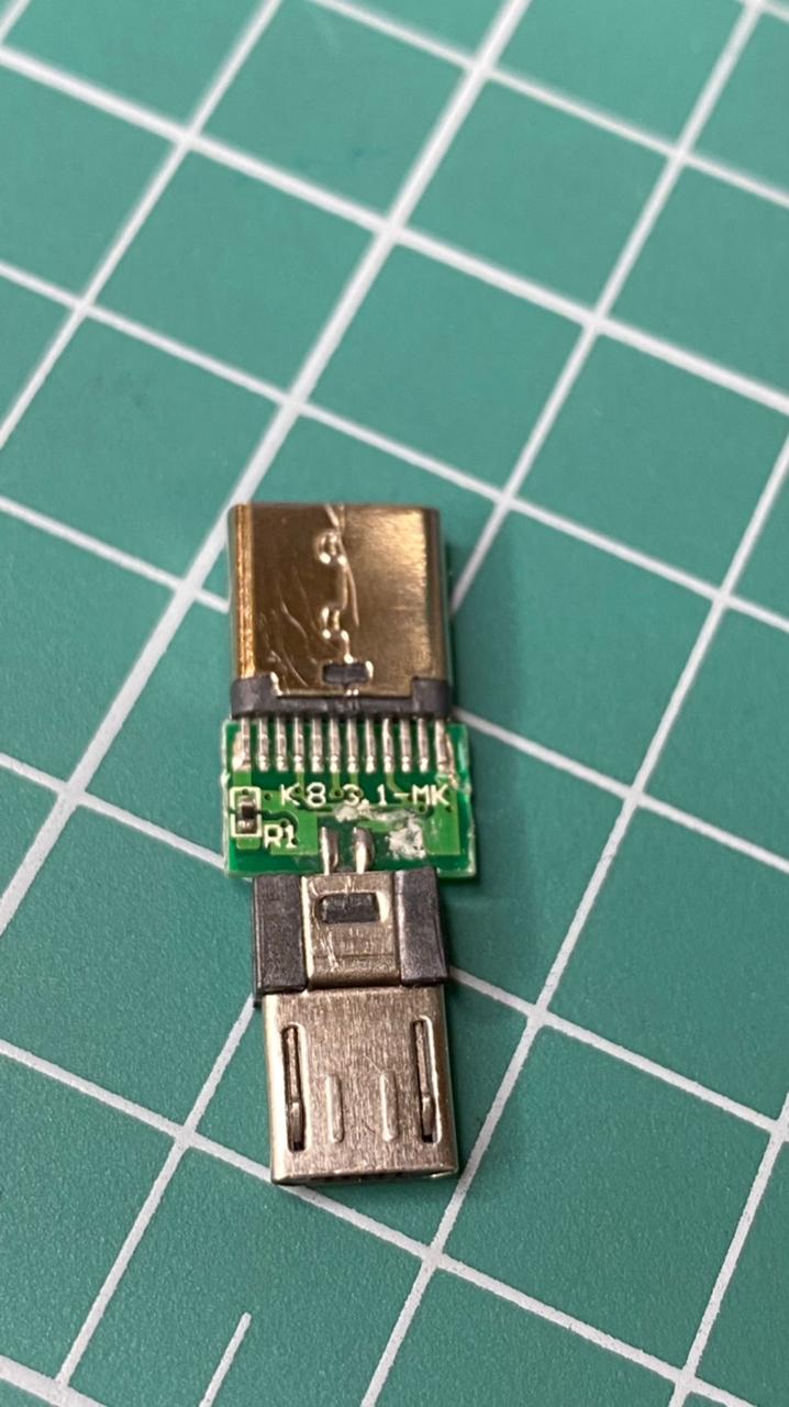
Regrettably these are 24 contact modules. Here are the manual instruction:

I know that the cc are the 5th pins. So I guess I can manage to to put the two resistors. What I don’t understand is which trace should I cut and why.

Any help would be greatly appreciated. Thanks in advance.

1 Like

The trace cutting is unique to the USB module used in this description I think.
I’m not sure how well the adapter you bought will work, but assuming it works, you should be able to just use it as is with no additional modifications.

I don’t know enough about USB to fully understand it. But, if the idea is to cut both CC->GND traces, put a 4.7k-5.1k resistor between them, and then splice Vbus and GND, that’s enough. I can then check the CC pins against the traces and see if I can put a resistor somewhere there. But I would need a confirmation that that is the idea.

1 Like