I’m converting a xeno chassis to a proffie and I want to use the usb c board at least as a charge port. I’m not sure how to hook it up though. There is battery, ground, and 5v. I don’t need data but if there is an easy way to do that I’m not opposed. Thanks in advance.
I’m not familiar with that particular USBC board, so I’d double-check to see where this “Battery” pin is going/was going w/ the Xeno first… (it might already be setup in such a way that you can rewire it w/ a proffie, so knowing more about how everything was wired prior would be helpful)
If we make the assumption (code for “take what I’m about to say with some salt”) that the 5V and GND directly connect to the USBC port, then with a Proffieboard v3 it should be very straightforward to simply connect the 5v to the VUSB pad on the board, and GND to GND, since PBv3 has builtin USB charging (@ 480mA), that should “just work.”
If you have a proffieboard V2, it’ll require an external charging circuit, you can’t just directly wire it up. There’s relatively common 5V Li-Ion battery charger breakout boards, but they’re all rather large if you’re working in an existing chassis…
Unless the port/USBC board you have has data pins exposed, there’s not a way to allow data via that port, but if there are, then it’s simply a matter of hooking them up to the D+ and D- pads on the PBv3.
Ultimately this likely hinges on whether or not you’re using a PBv3 (as far as doing it easily), though it’s possible w/ something like this and a proffieboard v2 (there’s also similar modules like shown in this image which you could use the existing port with), but those solutions take up a fair bit of space.
Sorry I should have mentioned I have a v2. Trying to use my v2’s I have laying around.
Second the port is built into the board.
Do you have a link to the 5v charging boards? Do you have a hookup image. For the v2. I saw something where they wire it into the existing micro usb port. Is that for data and charging or just data. I’m ok with just using it as a charging port. I’m trying not to add a 5.1 plug.
Thank you again for responding
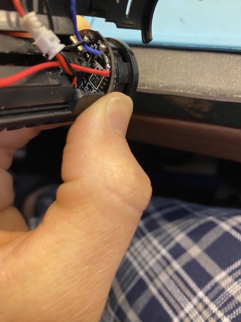
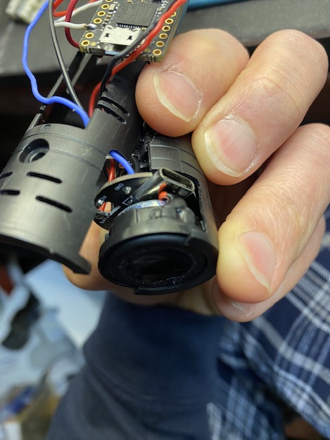
Here’s a picture of the usb board it’s on the top. I’m currently having issues powering on my proffie, so I’m trying not to take it apart at the moment.
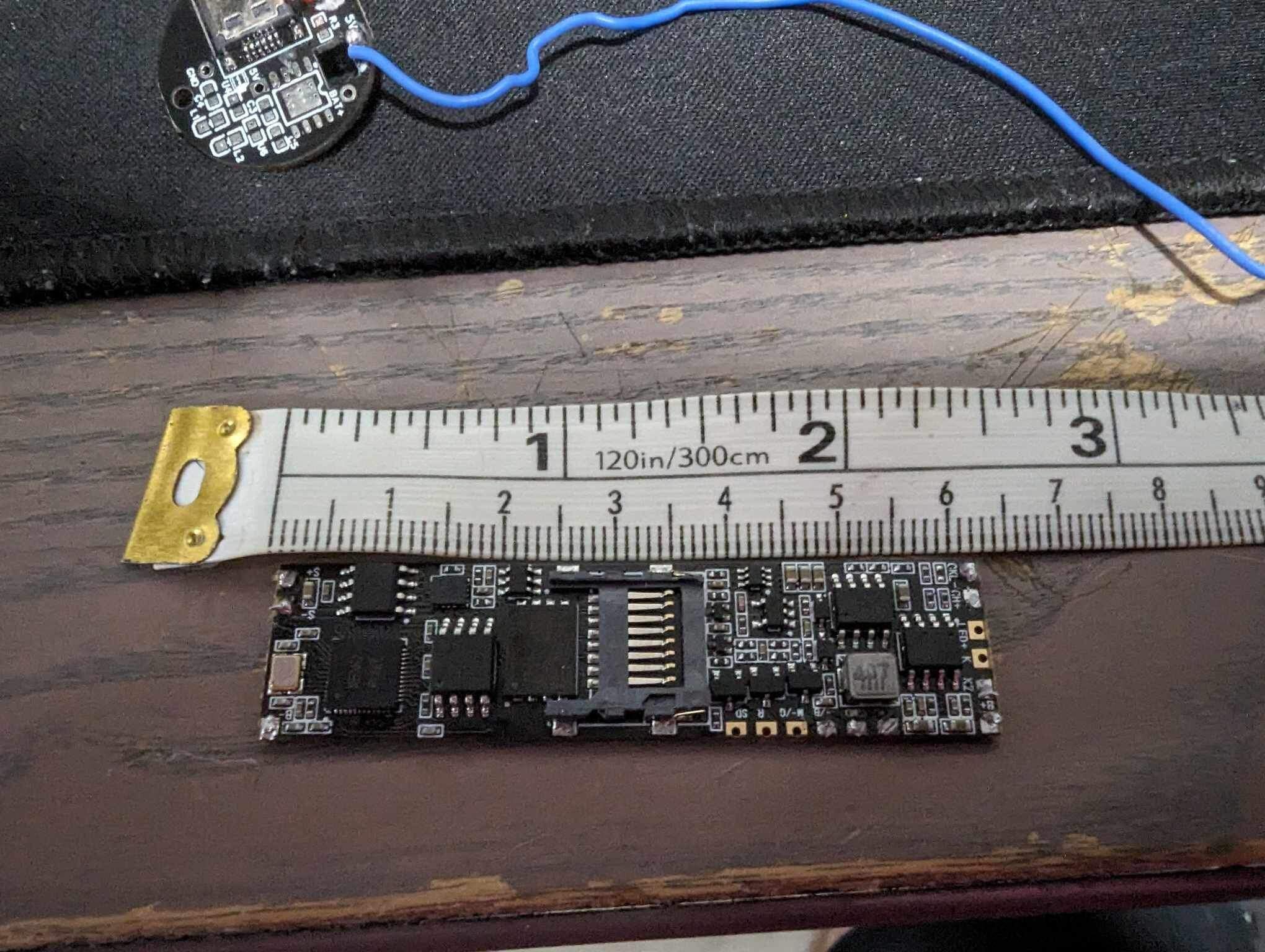
Interesting, it looks like there’s pads for all the stuff you’d expect for a Li-Ion USB battery charger, but it’s all missing (maybe used in different designs?), so you’d only get 5V out of that guy.
If you’re using a V2 then yeah, you’d need an external charger (in theory you could figure out that board and solder on the components for this one, but that’s a can of worms beyond the scope of this conversation I think…)
I don’t see breakouts on that PCB for data, so you wouldn’t be able to wire that up. What you saw with plugging into the proffieboard USB is relatively common for an external port, but you need the external port to have the data pins for it to be useful, otherwise all you’ll be able to do is power on the board while it’s on USB power… not connect/transfer data.
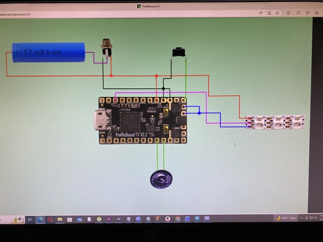
Your best bet if you want to use that port for charging is to try and fit an external charger PCB in there and wire it up, or you could even try using a different USBC port breakout that has data, then use it in conjuction with a charger PCB to basically recreate the circuit in that diagram I shared previously. It’s for CFX, but it gives you an idea of how it would work…
I don’t have a diagram for proffie (tried to find one but couldn’t get a good one…). As far as a link to that kind of charging circuit stuffage itself, you’d ultimately combine a microB breakout for the proffieboard itself with a USB lithium-ion battery charger (ignore the usb port, you can wire it up directly…), and if you wanted to retrofit the USBC port to use data, you could try modifying the chassis to use one of these USBC breakouts and replace the board that’s there rn. If you ditch data all you’d need is the USB lithium-ion battery charger PCB. (Would just wire things up according the diagram the same, ignoring the microB breakout and use the 5V and GND pads on the existing board instead of the USBC breakout)
EDIT: The Saber Armory actually sells these also, if you’re in the UK, and there’s a nice wiring diagram on that product listing.
So I can use that board to charge. All I need is the battery positive to the battery and the ground to battery negative and it will charge?
Do I need the 5v? Or should I hook the 5v to battery positive?
Thanks
On the charger PCB, N- goes to GND on your USBC PCB, N+ goes to 5V, B- goes to battery negative and B+ goes to battery positive.
Definitely do not connect battery + and 5V
Ok, I was thinking that this board already installed was a pcb and I could just connect positive and negative to battery, what threw me off is normally with a 5.1 port there is a third leg to ground.
It is, PCB just stands for “Printed Circuit Board,” but in this case it’s missing all it’s components so the only useful pads on it are the 5V and GND that (presumably) connect directly to the USBC port. It is highly unlikely the Battery pad on the board you have is even connected to anything.
No, because if you have 5V+ and GND, the battery charges at 4.2V (and really that’s typically varied by a smart charger a bit depending on what point it’s at in the charging cycle), so feeding it 5V would best-case just trigger the overvoltage protection, worst case you’ve made a spicy pillow.
I guess I’m not sure what you’re referring to when you say “5.1”? Do you mean a 2.1mm Recharge Port/Kill Switch? In that case, that additional leg is to allow cutting power to the board while charging, as well as acting as a kill/power switch. In this case, the board simply remains on while the battery is charging.
Yeah, I was talking about the charge port sorry. I’ve never installed a usb so I was comparing.
I see what you guys mean with no resistors etc. sorry about that. I’ll pick one up and add it.
I appreciate all the patience with me.