For a very long time, I’ve been wanting to try to guess the clash location based on gyro/accelerometer data. I’ve collected and plotted clash data before, but this time I got serious and applied some machine learning to the problem.
First thing I did was to create a better clash recorder. It lights up a small section of the blade, waits for a clash, and then asks if I want to save it. The saved data contains the accelerometer and gyro data, along with the computed “down” vector, saved 1600 times per second. The saved data has 256 rows, 128 of which are before the clash, and 128 are after the clash. The saved data also contains the location that was highlighted.
Next, I recorded 150 clashes, each at a random location on the blade. Then I copied the saved data to my computer and fired up TensorFlow.
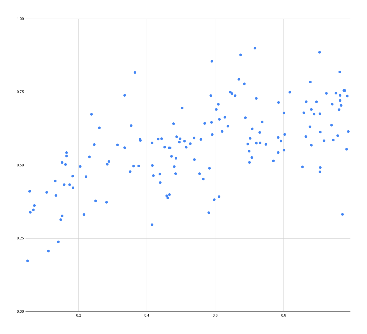
Unfortunately, TensorFlow doesn’t seem to be able to find a correlation between the data and the location, the best it seems able to do looks something like this:
In this scatterplot, the X axis is the highlighted point on the blade, and the Y axis is the predicted point. In an ideal world, these points should form a 45-degree line. As you can see there is very little correlation between predicted data and real data.
Unless I’m using TensorFlow wrong in some way, I think that means that it’s unlikely that we can find a correlation between the accelerometer/gyro/down data and the clash location.
Could the scattering just just be the limitations of the device? I mean if you look at the points far enough back they are in that general area. Drop the sample rate and see what the point look like then and run the analysis. As in more “focal group” less “crowd sample”.
I have no idea what you are suggesting.
Reducing the sample rate just means we’ll have less accurate data as input, leading to more garbage in → garbage out.
I’m not sure how to put it into terms that apply to Proffie so bear with me as I try to articulate. Remember I’m used to vehicles and planes not sound boards. In my mind it covers how the samples are being taken. Maybe instead what I should ask is how the samples are taken and what overall factors are in each sample. Like does the sample set include things that can be slightly changed or even switched to include alternate sources. Hopefully that makes sense. Refine what’s being looked at to better the test answers bringing them more into line.
The point of using machine learning is that I can throw all the data at it, and it should[1] be able to pick up the signal, if there is one. So that’s what I did. If that worked, I was going to try my best to find out what that signal was and write my own algorithm for detecting it. However, the signal found by the machine learning framework is super weak, making it almost useless, and that’s before I started reducing the input data, reduce the size of the model or using cross-validation. (All of which will make the error larger.)
If the machine learning framework is powerful enough
Ok that I get. I was going to ask “Were you swinging the saber during these clash tests that the machine looked at?” Like maybe latency accounts for the scattered spots where swing speed may be a factor.
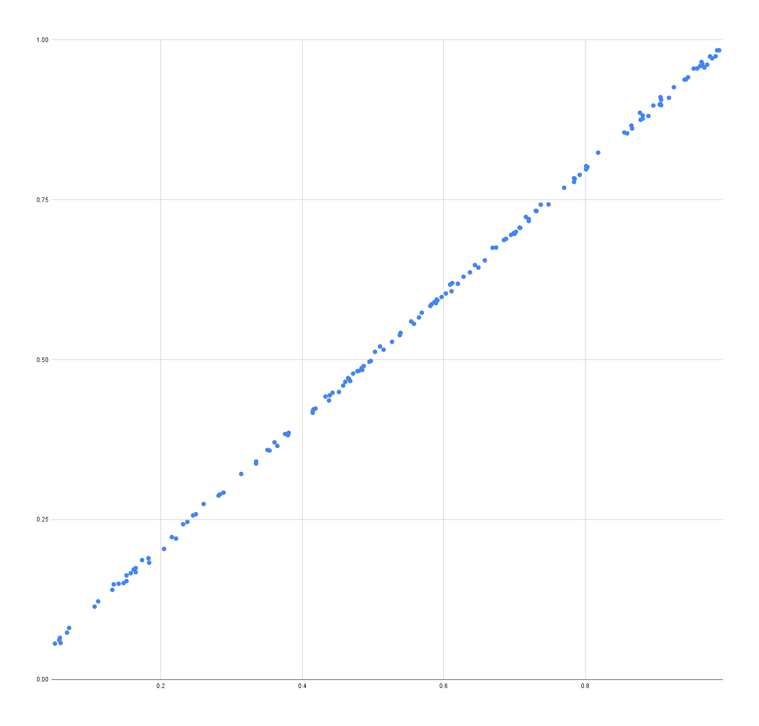
Turns out that the “good” result above is misleading though.
I was being lazy with the machine learning and used the same data to train and evaluate the TensorFlow model. The model didn’t learn how to predict clash locations, it simply learned how to recognize answer for each of the inputs I provided. It’s like learning the answers to a math test instead of learning how to calculate the answers; works great if you get the same test again, but not so great if it’s a different math test.
When I separate the training data from the evaluation data, the results aren’t nearly as good. In fact, they are worse than my first picture above. It’s not entirely bad news though. I might be able to reduce the complexity of the model to a point where it can’t remember all the answers anymore, and that might encourage it to learn the real thing instead. There might be other techniques I can use as well, or maybe, I just need to feed it more data. So while the outlook is a bit grim at the moment, there are still some avenues to explore.
I’ve listened to engineers deal w the same on dynamic controls. Apply that first bit and run the tests as ongoing tweaking the math as you go, take a break, go out and swing a saber, have some tea, have a brilliant thought, go back to it.
Looks like piezo-electric disks can be used to pick up vibrations.
Maybe I can use that to detect a clashes. If sampled fast enough, I might be able to pick up the reflected wave and learn how far up the blade the clash happened.
So nice to see science and science fiction clash like this. Just a thought: I have used ordinary microphones to locate taps on a surface, with very accurate results. I’m not suggesting a microphone is the right sensor in this case, but I do reckon an I2S sound input card would do high speed sampling of that piezo vibration sensor for you with minimal hassle. The data from the wave and its first reflection at the top would be better with, say, 96k samples per second to analyze. It is a sound wave, after all.
As a side note: Hi! I don’t think you remember me, but we met ages ago at Linköping University during your brief assignment there. I was a PhD student at the time. 1992, was it? (Your name is unique enough for me to have a flashback.)
Instead of using an I2S sound input, I was thinking of using analogRead directly from a small microprocessor, like maybe a pic. Once a potential clash is measured and located, it could send the information to the Proffieboard using serial or I2C.
I worry about being able to tell the difference between clashes and sounds generated by the speaker though.
PS: You are correct, unfortunately I do not remember you, but well met (again) anyways!
Most small boards seem to have a slow analogRead, limiting the sample rate to less than what you would want for analyzing an impulse with microsecond-accurate timing. A longitudinal wave in polycarbonate travels at about 1500 m/s, so you would need tens of thousands of samples per second to locate the clash to within a few centimeters. A transversal wave travels more slowly, and it’s a lot stronger in amplitude, but I alos suspect it to be harder to analyze (more noise, weaker reflection and stronger ringing, wavelength-dependent reflection and wave propagation velocity). A dedicated sound input device has a much faster sample rate with little or no sample jitter, and it leaves the CPU free for other tasks.
If you use a piezo sensor, I wouldn’t think there is any risk of confusing speaker sounds with clashes. Vibrations due to physical hits ought to be orders of magnitude stronger than anything induced by sound.
If we could put one sensor at each end of the blade, this would be a much less difficult task, but of course I see the point in making it work for any blade without modifications.
Hmm. Perhaps this is what I should try instead of pursuing my current quest for a blindingly bright blade. I’m experimenting with fiber optics and thinking of water cooling, with my wife stopping me from entering mad scientist mode with death-murder-kill-strong lasers and sticking with LEDs, but those are all niche designs that would only be one-off builds for lols and bragging rights. I’m well into the realm of “don’t try this at home” already.
I don’t have an I2S input device, but I ordered one just now, along with some vibration sensors. I’ll post an update if I discover anything useful.
Slow analogRead would indeed be a problem, and I’m not actually sure what a small CPU would be capable of.
The STM32L4 series of chips can be configured so that analog reading is done fast or slow depending on how much precision you want, they can also be configured to trigger reads from a timer and the output can be stuffed into a DMA channel and written to memory. (When I say analogRead, don’t literally mean calling the Arduino analogRead function, since that would block the main CPU while the analog conversion is happening.)
However, I wasn’t planning to use the proffieboard cpu for all this. I’m thinking that a small external cpu would do the work. I just don’t know if they have similar capabilities or not.
I see two potential problems with using an I2S input device though:
I2S uses 3 pins, and can’t be shared with other functions. Proffieboards don’t really have a lot of extra pins.
The proffieboard CPU would need to analyze the audio, which could be somewhat cpu-intensive. It would be nice to offload that part to a sub-board.
Good points. Perhaps an I2S input unit and a small external CPU would be the way to go. My main issue is that sound input boards have much better ADCs than what you generally find on Arduino/Raspberry/etc analog inputs, and very tightly controlled sample rates. They generally have two input channels as well, which could be useful. But first I need to wire up some tests with my oscilloscope to determine which sensor to use. The ideal would be a $1 piezo buzzer membrane which is easily found as scrap, or a $1 microphone if it can be sealed off from picking up too much ambient sound.